
Home › How We Build Playgrounds › Playground Layout Design
Step 02 · Project timelinePlayground Layout Design: How We Turn Your Site Plan into a Zoned 3D Playground Before Quoting
Playground design for commercial sites, drawn by the design office of the factory that builds the equipment. Send a DWG, PDF survey or sketch; the zoned layout, a DWG on eight named layers, 3D renders and an itemized quotation come back within 3 working days.
Legend · layers in your DWG
- base
- zones
- equipment
- use zones
- surfacing
- footing points
- accessible route
- supervision positions
- 2D + 3D layout + itemized quotation in 3 working days
- DWG on your base and coordinates
- 8 named layers
- Second-designer check
- Designed to ASTM F1487 / EN 1176
Playground Design Services Layouts, Renders, Item Drawings and Installation Drawings
The design office produces every drawing on a Run Playgrounds project, from the first layout to the drawings your installer builds from: the drawing work of a playground design company, done inside the factory that makes the equipment.
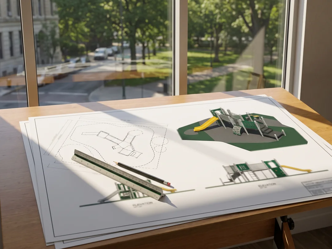

One layout by defaultOne layout comes back with your quotation. To compare, ask for an alternative within your budget range. How revisions work
| No. | Document | Format | Content |
|---|---|---|---|
| 01 | 2D layout | PDFDWG | A scaled PDF plan and a DWG plan on eight named layers, in ft-in for US projects, mm for EN markets, or both on one drawing. |
| 02 | 3D renders | JPG3D | Aerial and eye-level views of your site in your theme and colors; the 3D model file on request. |
| 03 | Single-item plans and elevations | One sheet for every piece on the layout, with its use zone dimensions and deck heights. | |
| 04 | Surfacing area table | TABLE | Area by surfacing type, taken from the surfacing layer. |
| 05 | Quotation lines | Priced line by line from the same equipment list, with the material spec sheet and the compliance document list. | |
| Issued after you approve the drawing | |||
| 06 | Installation drawings | DWGPDF | The approved layout becomes the installation drawing, with every part numbered to it. |
| 07 | Footing detail drawings | DWGPDF | Concrete footing size for every post, including swing beams, fitness stations and shade posts. |
| 08 | Part list | TABLE | Every part keyed to its structure number. |
The design office draws
Layouts, renders, single-item sheets, installation drawings and footing detail drawings for every post.
Your engineer or landscape architect reviews and stamps
The site design these equipment layouts and installation drawings sit in.
Your installer builds from
The installation drawings, the footing detail drawings and the part list, every part numbered to its structure.
Design Office Workflow Eight Steps and Eight Layers From Site Plan to Quotation
Every playground design leaves the office through the same fixed order. Each step adds one layer or one file, and nothing is placed until the layer under it is finished.
That is why the zones, the equipment, the surfacing and the price on your quotation agree, whether the drawing is a single spring rider on a school yard or a full park.
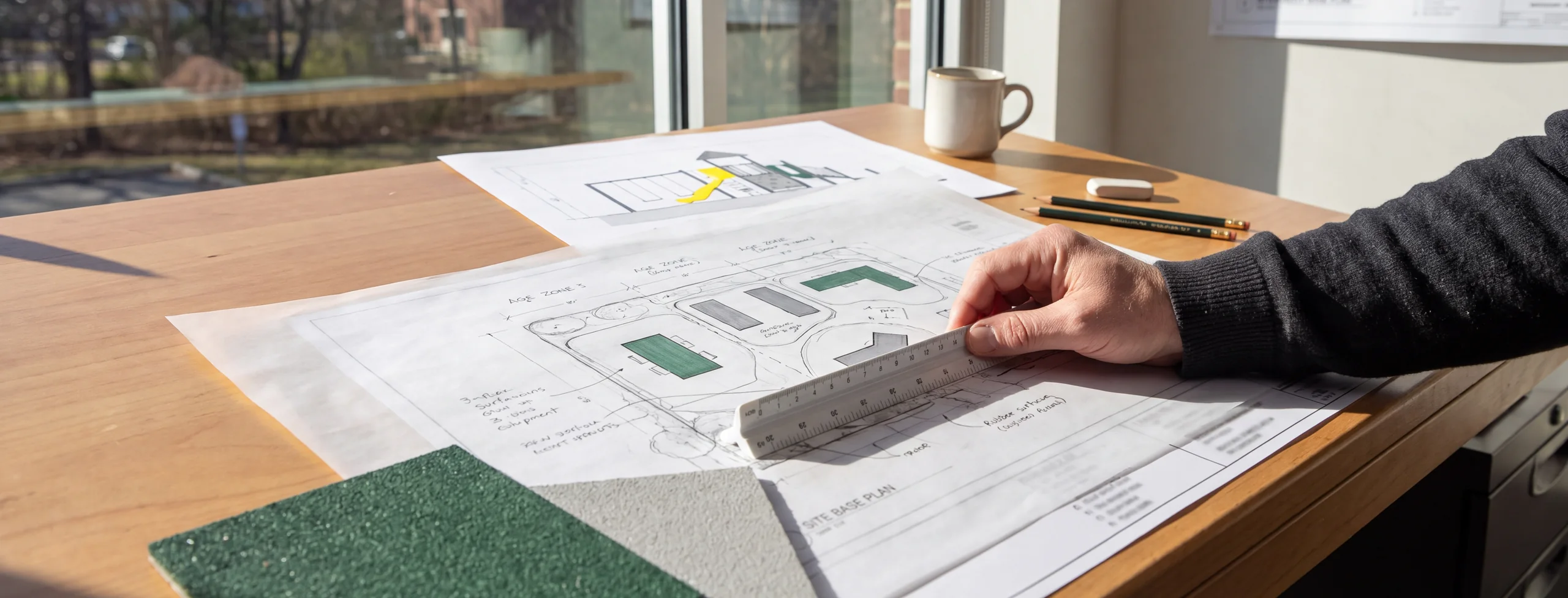
Step 01
Site base
Scale, boundary, north point, fixed objects, slope, ground type and access points are checked on what you sent. Missing items come back to you as a short list.
→ Layer · base
Detail ↓Step 02
Zones
Age zones are blocked out before any equipment: 6–23 months, 2–5 years and 5–12 years, or the zones your EN 1176 site calls for, with circulation and adult supervision points.
→ Layers · zones · supervision positions
Detail ↓Step 03
Equipment
Structures are composed from Ø114 mm posts, decks, 19 mm HDPE panels and 304 stainless fasteners. Each gets its structure number here, S1, S2: the prefix of every part number.
→ Layers · equipment · footing points
Detail ↓Step 04
Use zones
A use zoneThe clear area around a piece of equipment that must stay free of other equipment and fixed objects, set by the project standard. and fall zone goes around every piece, then is checked against every other zone and every fixed object. A clash sends the piece back to step 3.
→ Layer · use zones
Detail ↓Step 05
Surfacing
The critical fall height of each piece sets the surfacing type and thickness under it. Extents go on the surfacing layer with an area table; the accessible route runs from your entrance.
→ Layers · surfacing · accessible route
Detail ↓Step 06
Standards check
A second designer checks the finished drawing against the checklist for your standard before it leaves the office.
→ Check · every layer
Detail ↓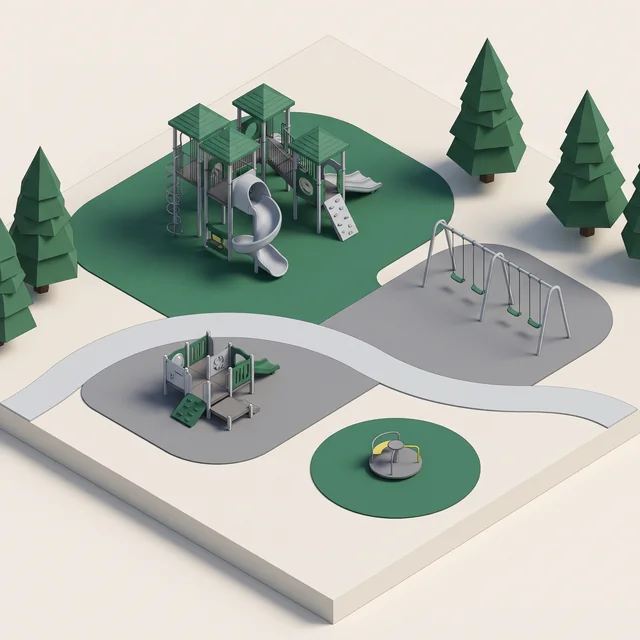 Same model as the 2D plan
Step 07
3D
Renders are made from the same model as the 2D plan, so the structure in the render is the structure on the plan.
→ File · JPG renders
Itemized quotation · lines
- S1Multi-deck structure
- S2Toddler structure
- S3Two-bay swing set
- SFSurfacing · type A · area from layer
- SFSurfacing · type B · area from layer
Step 08
Quotation
Your project manager prices the equipment list and the surfacing area table of the finished layout. Layout and quotation come back together.
→ File · itemized quotation
Detail ↓
Site Inputs We Accept DWG, PDF Surveys, Sketches and Satellite Screenshots
The design office starts from whatever drawing of your playground site plan you have. Anything missing comes back to you as a short list, with a request for photos from each corner of the site.
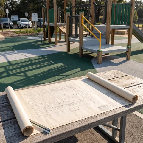
DWG / DXF
Drawn on your base and your coordinates; the DWG-compatible files that come back line up with the rest of your plan set.
Base = your drawing · your coordinates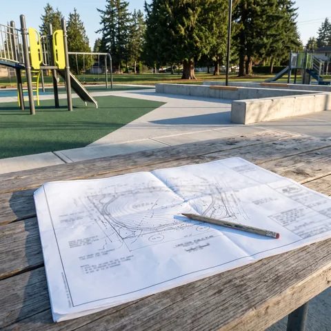
PDF survey
Redrawn to scale as the base layer, with the dimensions taken from it marked for you to confirm.
Base = redrawn to scale · dimensions marked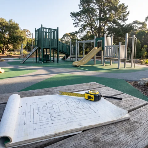
Dimensioned hand sketch
A starting point: the first layout is drawn to your dimensions, then confirmed before approval.
Base = your dimensions · confirmed before approval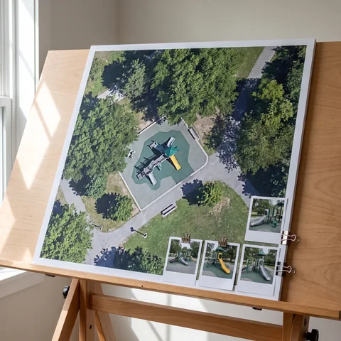
Satellite screenshot + site photos
A starting point: the dimensions are confirmed before the drawing is approved.
Base = starting point · confirmed before approval
Whichever you send, it becomes the base layerThe first layer of your drawing: your site, its boundary and fixed objects. Everything else is drawn on top of it. of your drawing.
Alongside the drawing, send
- Age groups and expected visitors
- Theme and colors
- Budget range
- The standard you build toASTM F1487 and the CPSC handbook · ASTM F2373 for under-2 areas · ASTM F1918 for indoor soft play · or EN 1176
- Photos of the site from each corner
- Fixed objectsTrees, poles, drains, gates
- Slope, ground type and access points
Column positions, clear ceiling height, entrances and fire exits.
How those inputs shape an indoor drawing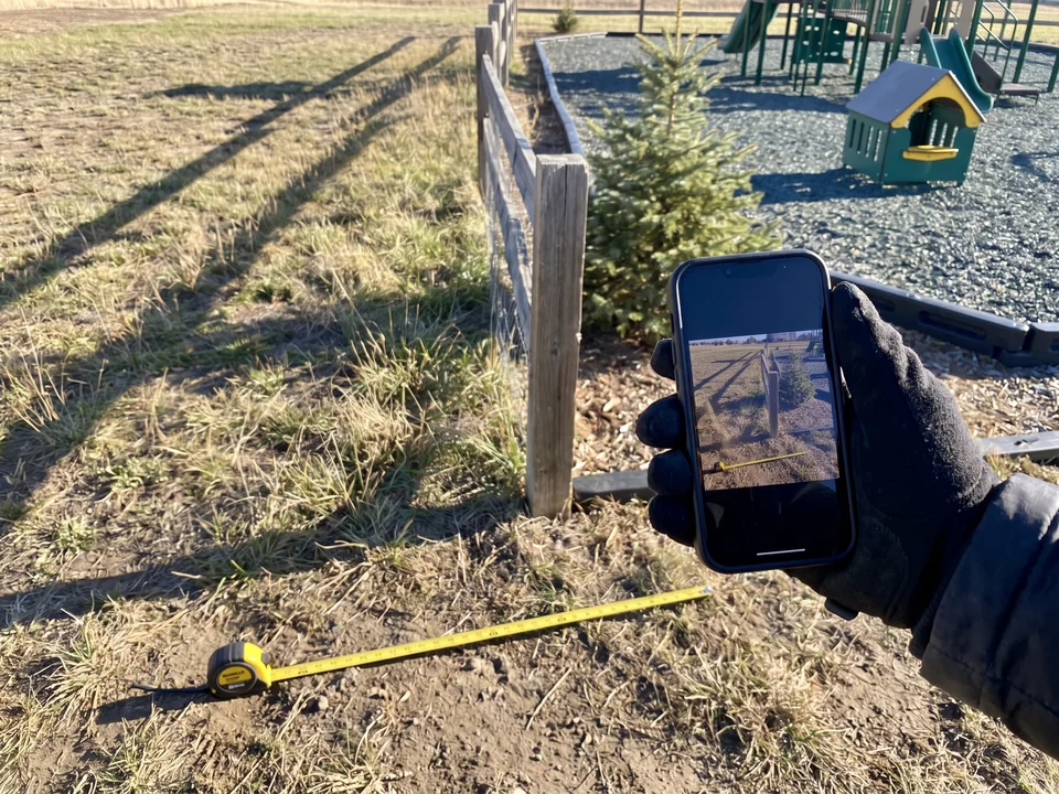
Anna, Sales Manager, receives your files, replies within 24 hours on business days and returns the layout from the design office within 3 working days.
Send your DWG, PDF or sketch, age groups and standard to Anna on WhatsApp. Layout, DWG and itemized quotation come back within 3 working days.
Drawing Files for Your Plan Set DWG on Your Coordinates, Eight Named Layers, PDF and Renders
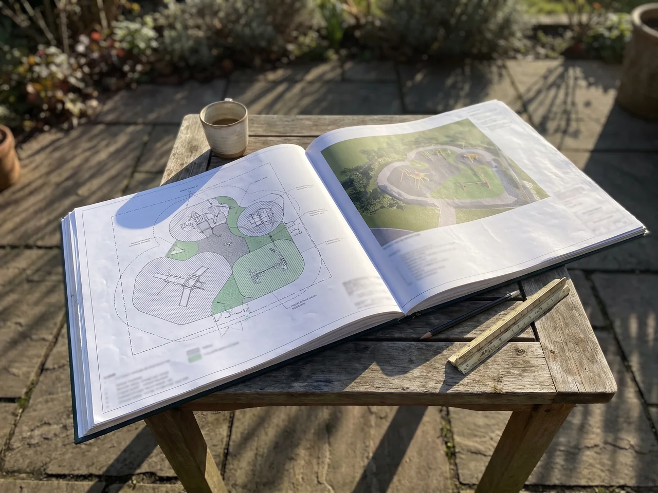
For landscape architects, planners and specifiers, the layout is a file you place into your own design, and these playground DWG drawings are made for that.
The designer works inside your drawing, on your coordinates, so the equipment, use zones and surfacing sit where your paths, planting, drainage and site furniture already are.
Overlay the layers on your plan without re-scaling or moving anything. The returned files are DWG-compatibleFiles that open in the CAD software your office already uses, on your own drawing units and coordinates.. Switch the use zones layer on over your paths, tree canopies, benches and drainage, and any overlap shows at once.

| Linetype | Layer | Carries | Goes to |
|---|---|---|---|
| base | Your site, fixed objects and boundaries | You | |
| zones | Age zones and circulation | You | |
| equipment | Every structure and freestanding piece, each labeled with its structure number | You, your installer | |
| use zones | Use zone and fall zone around each piece | You: check it against your design | |
| surfacing | Surfacing extents by type | You: against your paving edges | |
| footing points | Post positions | Your structural engineer | |
| accessible route | Route from the site entrance to the play equipment | You | |
| supervision positions | Adult and staff positions and sightlines | You, the operator |
Units
ft-in for US projects, mm for EN markets, or both on one drawing if your plan set needs both.
PDF and renders
A scaled PDF plan for review and mark-up, and JPG renders from aerial and eye-level views for client, board or tender presentations. The 3D model file on request.
Who stamps
These are equipment layouts and installation drawings. Your engineer or landscape architect reviews and stamps the site design, with these files inside it.
Revisions
Comments come back as revised files on the same layers and the same coordinates, with the quotation updated to match. Revisions and approval
Single-Item Plans and Elevations Use Zone Dimensions and Deck Heights for Every Piece
Every piece on your layout has its own sheet, so you can place it in your detail pages or tender documents on its own. Its values are drawn from your layout.
For tenders
Schools and parks departments can also request editable specification text and a data sheet for every item, next to the material spec sheet and the compliance document list. How those files are used in a school tender
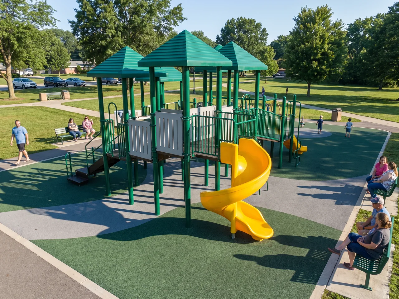
Multi-deck structure
Deck heights + use zone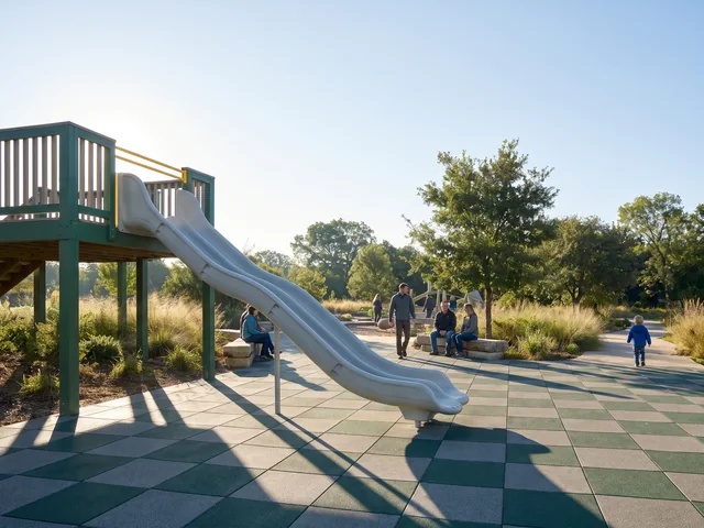
Slide
Start deck height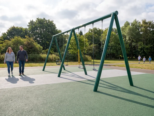
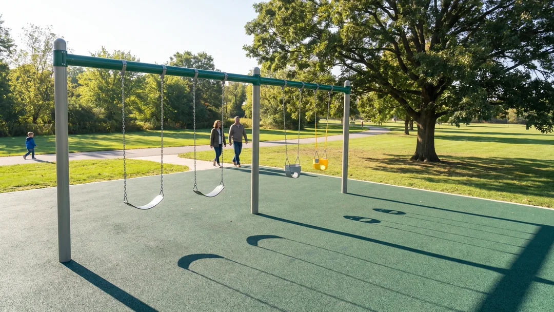
Swing set
Use zone + top beam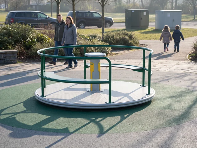
Merry-go-round
Use zone around the deck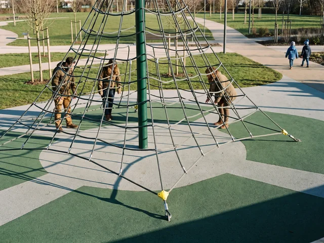
Rope and climbing net
Use zone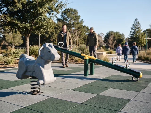
Spring rider and seesaw
Use zone + base plate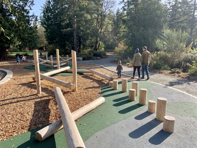
Nature play
Use zone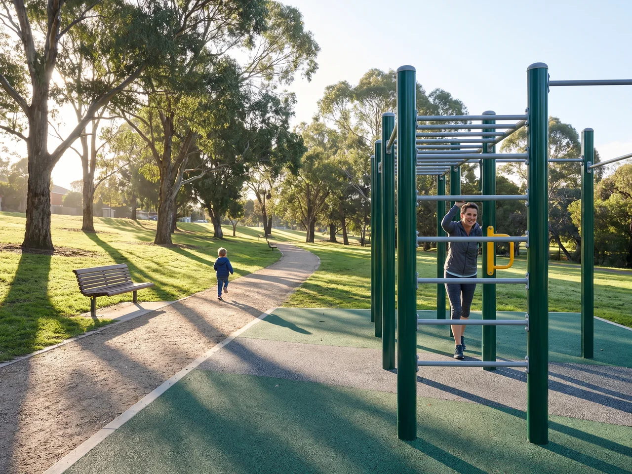
Outdoor fitness
ASTM F3101 / EN 16630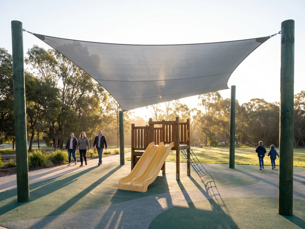
Shade structure
Post positions
Plan
Elevation
Single-item sheet
Multi-deck structure
Plan and elevation with deck heights and use zone dimensions.
Plan
Elevation
Single-item sheet
Swing set
Plan with the swing use zone and elevation of the top beam.
Plan
Elevation
Single-item sheet
Merry-go-round
Plan with the use zone around the turning deck.
Plan
Elevation
Single-item sheet
Rope and climbing net
Plan and elevation with the use zone.
Plan
Elevation
Single-item sheet
Spring rider and seesaw
Plan and elevation with the use zone and base plate.
Plan
Elevation
Single-item sheet
Nature play
Plan and elevation with the use zone.
Plan
Elevation
Single-item sheet
Outdoor fitness
Plan and elevation with the use zone, designed to ASTM F3101 / EN 16630.
Plan
Elevation
Single-item sheet
Shade structure
Plan and elevation with post positions over the structure they cover.
Use Zones and Fall Zones Clash Check Against Every Zone and Fixed Object
Use zones decide where equipment can stand and how much surfacing the site needs, so the design office draws them before it prices anything.
Scroll to run the check, or
What this check found
- Step 04 · clashThe swing set's use zone ran into a tree canopy; the spinner's use zone ran into the gate.
- Step 03 · againThe swing set moved clear of the canopy and the spinner moved beside S1, on the equipment layer.
- Step 04 · clearNo zone overlaps a zone or a fixed object, so the drawing moves to the second-designer check.
Drawing the use zones
The designer draws a use zoneThe clear area around a piece of equipment that must stay free of other equipment and fixed objects, set by the project standard. and fall zoneThe part of the use zone where a child can land in a fall; it is covered by impact-attenuating surfacing. around every structure, swing bay, spinner, spring rider and fitness station to the standard your project names: ASTM F1487 and the CPSC handbook, ASTM F2373 for under-2 areas, or EN 1176.
Each zone sits on the use zones layer, separate from the equipment it belongs to, so it can be checked on its own.
The clash check
Every use zone is checked against every other use zone and against the fixed objects on the base layer: trees, poles, drains, gates and your access points.
Where two zones overlap, or a zone runs into a fixed object, the designer goes back to the equipment layer and moves the piece, turns it or changes its configuration. The drawing goes out once the use zones layer is clear.
What you receive
The use zones stay on their own layer in your DWG, ready to check against your design. How the layers work in your plan set
Surfacing Layer Area Table by Surfacing Type, Priced Line by Line
The surfacing layer turns fall heights into an area table, and the surfacing lines on your quotation are that table.
01 · Fall height → thickness
The critical fall heightThe height a child can fall from a piece of equipment; it sets how thick the surfacing under that piece must be. of each piece sets the rubber tile or poured-in-place EPDM thickness under it, to ASTM F1292 in the US or EN 1177 in EN markets.
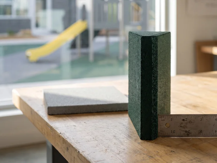
Thickness set by fall height 02 · Surfacing layer
The extents cover the use zone of each piece and are grouped by type and thickness. Accessible surfacing along the accessible route is drawn to ASTM F1951.
03 · Area table = quotation lines
Area table · from the surfacing layer Type Material Thickness Area Type A Rubber tile By fall height From your layer Type B Poured-in-place EPDM By fall height From your layer Accessible route ASTM F1951 Along the route From your layer Your quotation · surfacing lines Line Material Quantity Surfacing · Type A Rubber tile = area table Surfacing · Type B Poured-in-place EPDM = area table Surfacing · Accessible route ASTM F1951 = area table
If a revision moves a piece or changes its fall height, the surfacing layer, the area table and the surfacing lines on your quotation all change with it.
Landscape architect
Checks the surfacing extents against their own paving and planting edges.
Installer
Uses the area table to plan excavation and base preparation.
Parks department or school
Puts the table into a tender next to the equipment items.
The surfacing is partner-built and inspected by our QC against that thickness before it is loaded, on the same container plan as the equipment. Materials and thicknesses are on playground surfacing.
The price on your quotation
is taken from the drawing on your screen.
Standards Checklist and Second-Designer Check Entrapment, Barriers, Protrusions and Use Zones
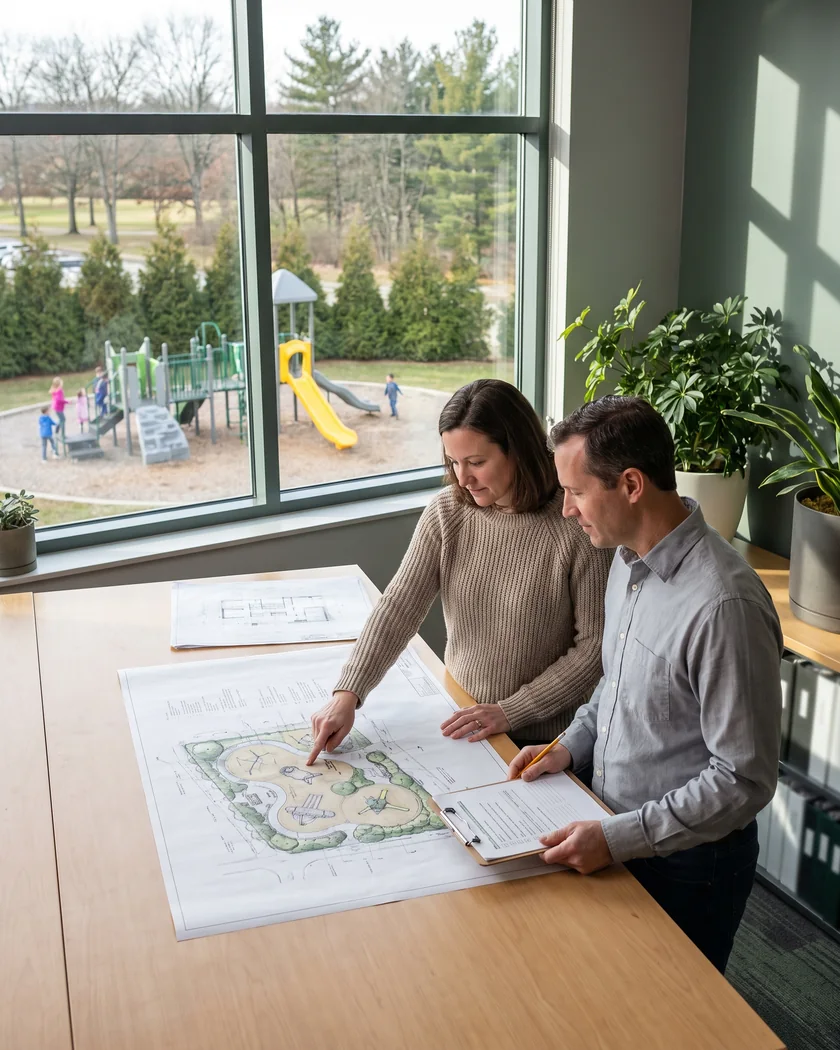
Every layout is checked twice before it leaves the design office. One designer draws; a second designer checks the finished drawing against the standards checklist for your project.
Comments go back to the first designer, and the drawing is sent only after the second designer has cleared every item.
Designer 1 · draws
Site base, zones, equipment, use zones and surfacing, in the fixed order of steps 01–05, then the 3D from the same model.
- base
- zones
- equipment
- use zones
- surfacing
Designer 2 · checks against your standard
Each item is cleared on the drawing itself, not on a summary.
Standard named at step one
ASTM F1487 and the CPSC Public Playground Safety Handbook, ASTM F2373 for 6–23 month areas, ASTM F1918 for indoor soft play, ASTM F2970 for trampoline courts, ASTM F3101 for outdoor fitness, or EN 1176 and EN 1177.
Head- and finger-entrapment gaps
On every opening of every structure.
Protrusions and sharp edges
None on any piece.
Use zones and fall heights
Every piece has a use zone on the layer, and no zone clashes.
Surfacing
Every use zone is covered on the surfacing layer to the fall height of its piece.
Accessible route
Drawn to the play equipment, planned around ADA accessible-route principles.
Supervision
Tall enclosed elements do not block the sightlines from the supervision positions.
The compliance documents for your standard are listed on the quotation that comes back with the drawing, and third-party testing is arranged per project on request. Each standard is explained on playground safety standards.
Structure Numbers on the Layout From Your Drawing to Quotation Lines and Part Numbers
The number a structure gets in step 3 stays with it through every file the design office produces. When the designer places a structure on the equipment layer, it gets its structure number: S1 for the first structure, S2 for the next.
DWG + PDF · equipment layer
Single-item sheet · S1
- S1Multi-deck structure
- S2Toddler structure
- S3Two-bay swing set
- SFSurfacing · type A
Quotation · line S1
Installation drawing · S1
 S1-014
Part · S1-014
Part 14 of structure S1
Comment on S2, and four people find S2 on their own document

Your project manager
S2 on the quotation
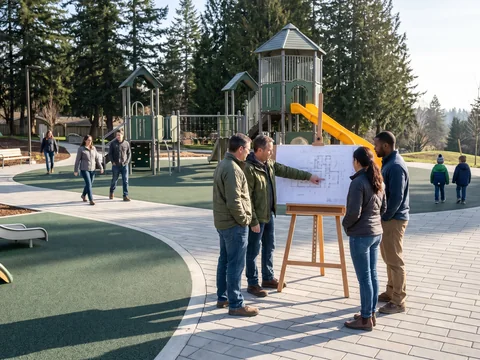
The designer
S2 on the drawing
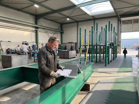
The workshop
S2 on every part
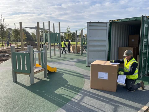
Your installer
S2 on the packing list
How the part numbers are carried through production, packing and shipment is on how we build playgrounds.
Confidential Base Drawings and Dealer Projects Your Plans Used Only for Your Project
Landscape architects, installers and dealers send drawings that belong to their own clients.
- 01
Used only for your project
Everything you send, from the DWG base and survey to site photos and marked-up plans, is used only for your project. Returned layouts are drawn for that site, never reused as another buyer's starting point.
- 02
Registered under your name
For dealers and installers, the project is registered under your name when you send the site plan.
- 03
Your end client is not contacted
Their details stay confidential.

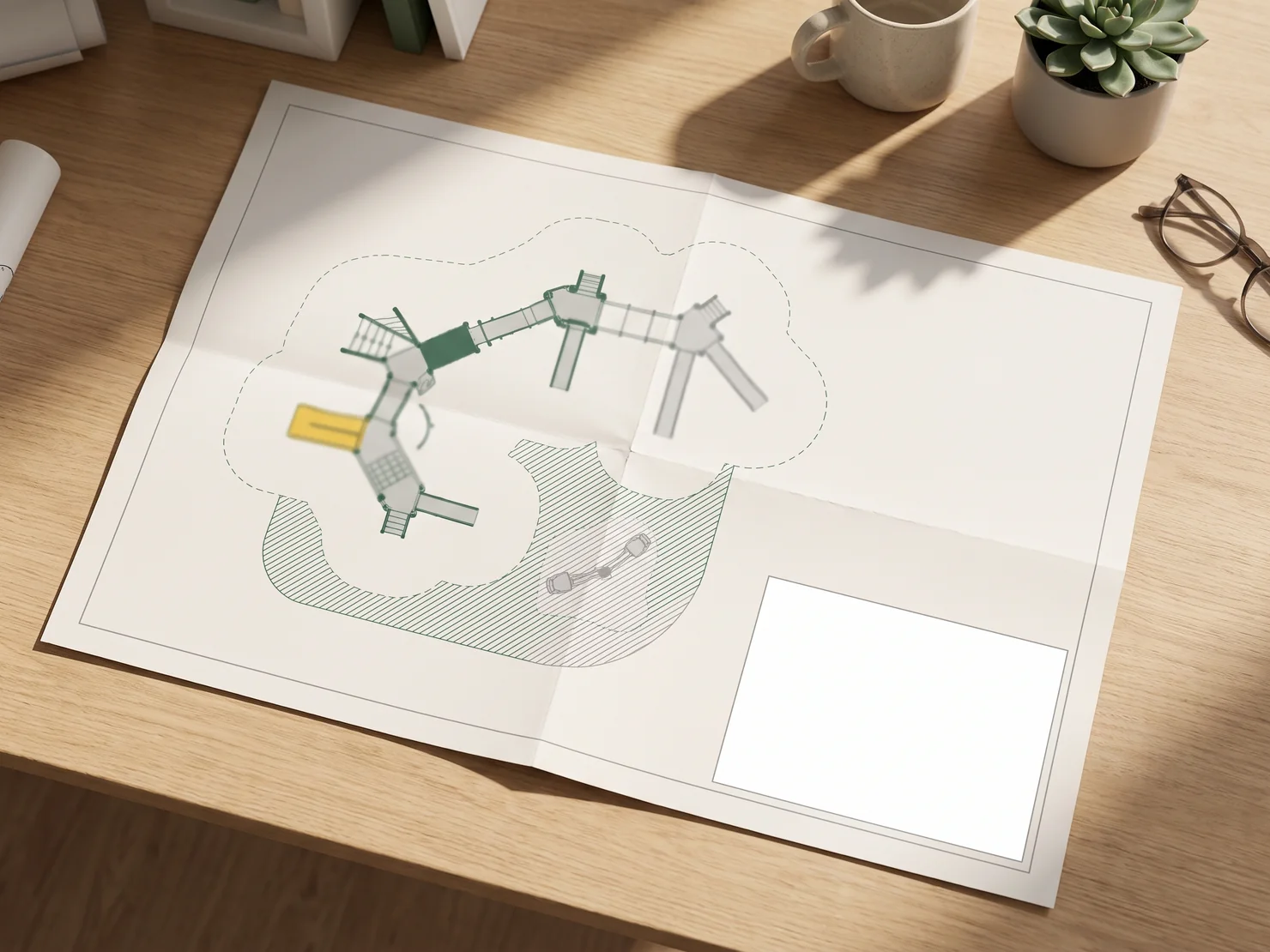
Unbranded or your brand
Layout drawings, renders and quotation files can be issued unbranded or under your brand, so the plan set you hand over carries your title block rather than ours.
For design teams
Because the drawing is made on your base and coordinates, the equipment layers drop into your own plan set without re-drawing, and your engineer or landscape architect remains the one who reviews and stamps the site design.
Dealer terms beyond the drawing stage are on wholesale playground equipment.
Revisions, Alternative Layouts and Drawing Approval
Rev A · first layout
One layout comes back by default, with the quotation priced from it.
Rev B · your comments
You comment, and the design office returns a revised layout on the same layers and coordinates, with the quotation updated to match. Revisions continue until you approve.
Alt · within your budget range
To compare, ask for an alternative layout within your budget range and it comes back beside the first.
Approved · frozen
At approval the layout is frozen and becomes your installation drawing, with footing detail drawings for every post.
After approval
A change after approval goes onto a revised drawing that you approve again.
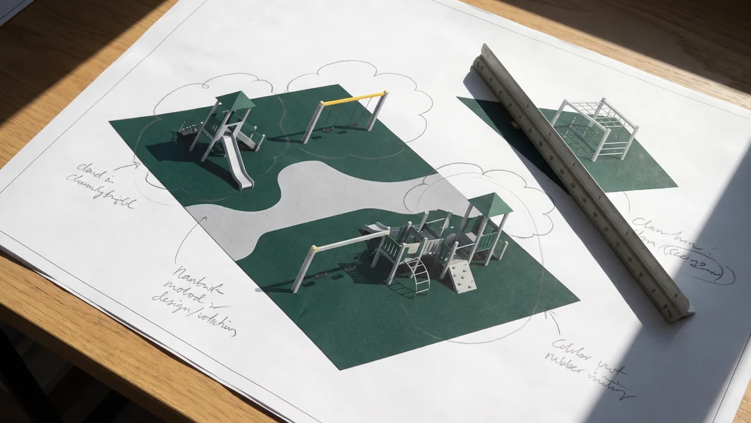
What locks on the approval day is on how we build playgrounds; themes, colors and logos drawn into the layout are on custom playground solutions.
Layouts for Parks, Schools, Daycares and Indoor Venues Same Eight Layers, Site-Specific Inputs
Dealers, landscape architects, parks departments, schools, daycare centers and FEC founders all get the same eight steps and eight layers. What changes is what goes onto the zones, supervision and base layers.
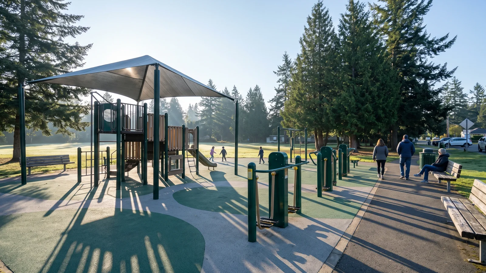
Parks and community sites
- zones · Age zones, shade over play and fitness beside play, on one drawing
- supervision positions · Benches and sightlines across each zone
Municipal tender files come with the drawing.
Outdoor equipment and zoning by age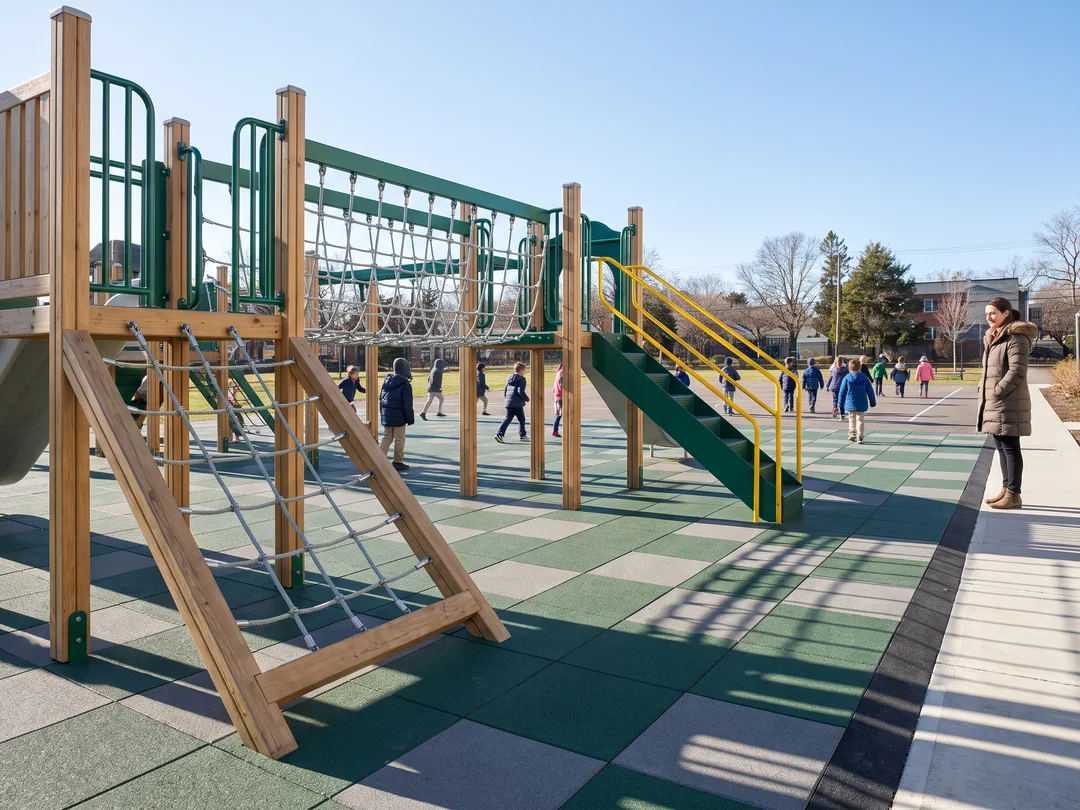
Schools
- zones · Drawn to the recess groups the school gives
- supervision positions · Sightlines across each zone
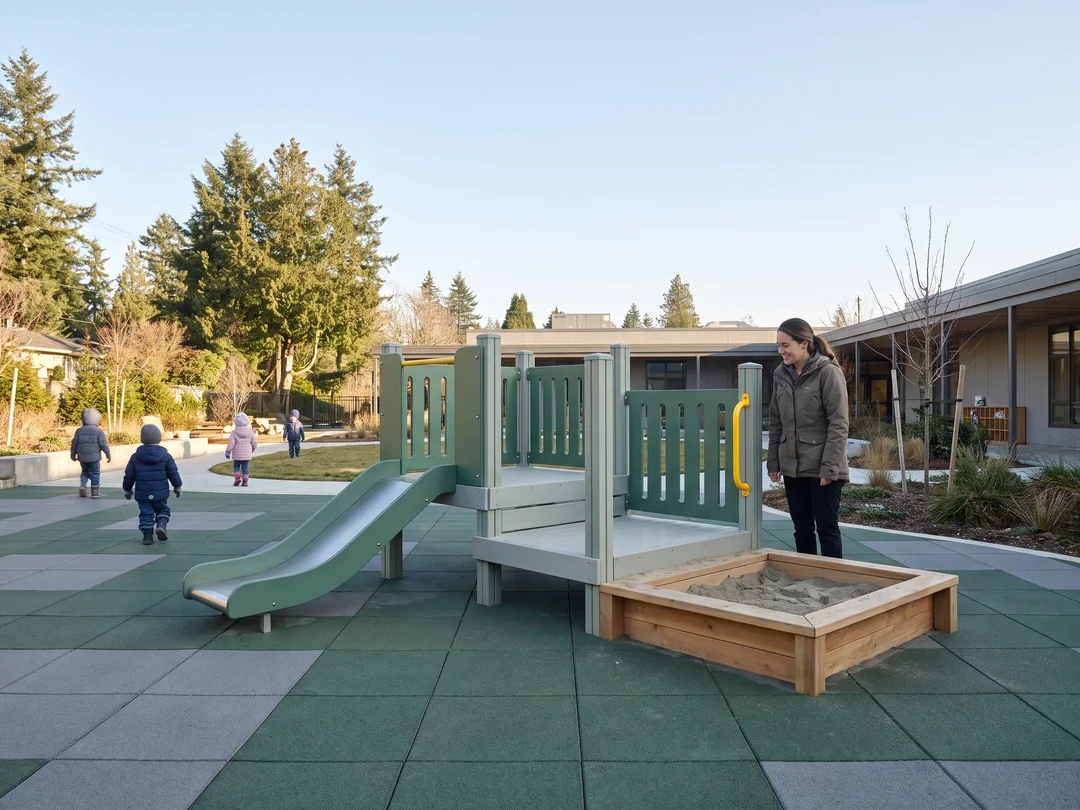
Preschools and daycares
- zones · Rooms mapped to zones, low-deck structures
- supervision positions · Staff positions marked on the drawing
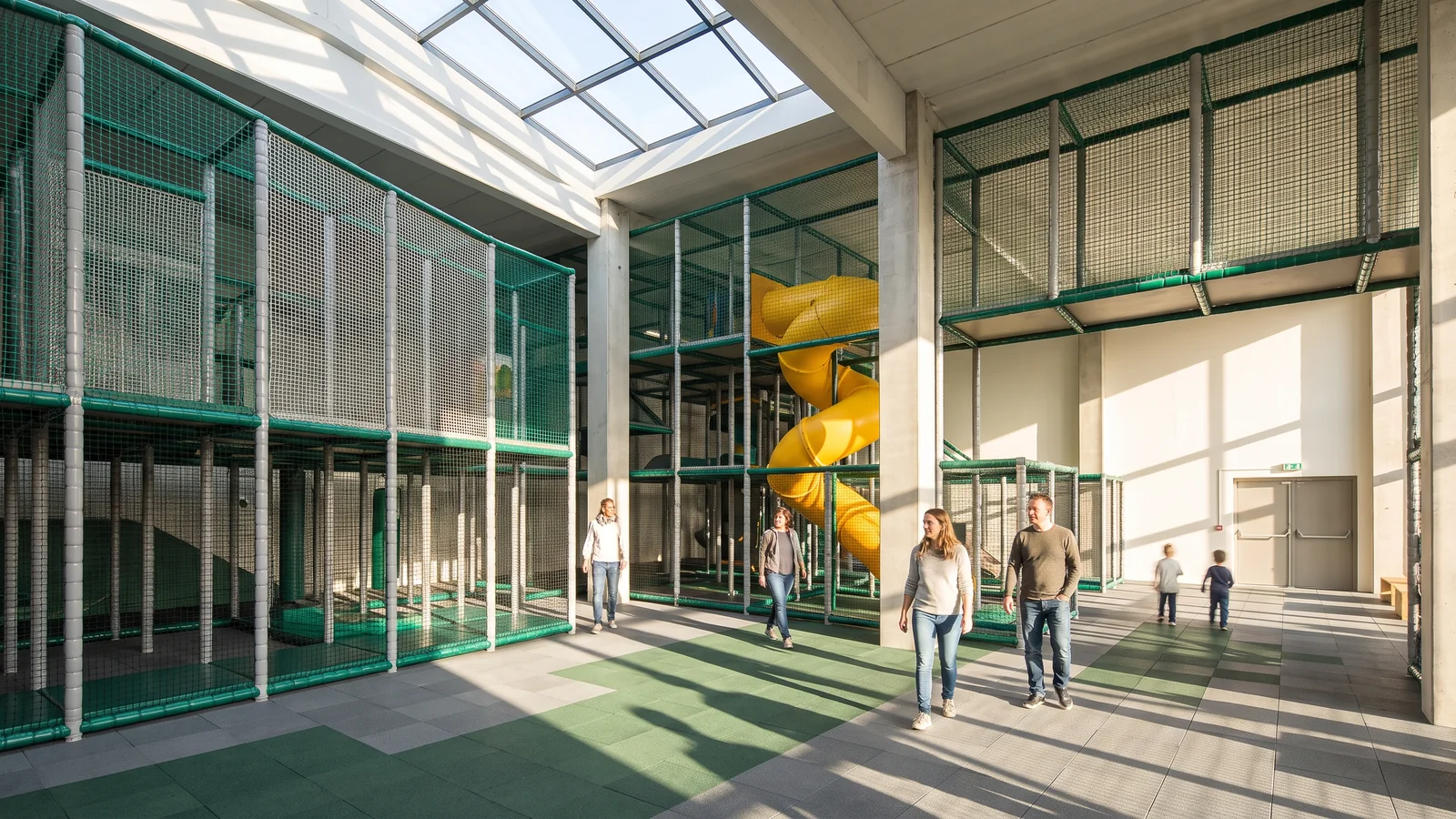
Indoor venues
- base · Columns, clear ceiling height, entrances and fire exits
- zones · Age areas fitted between the columns