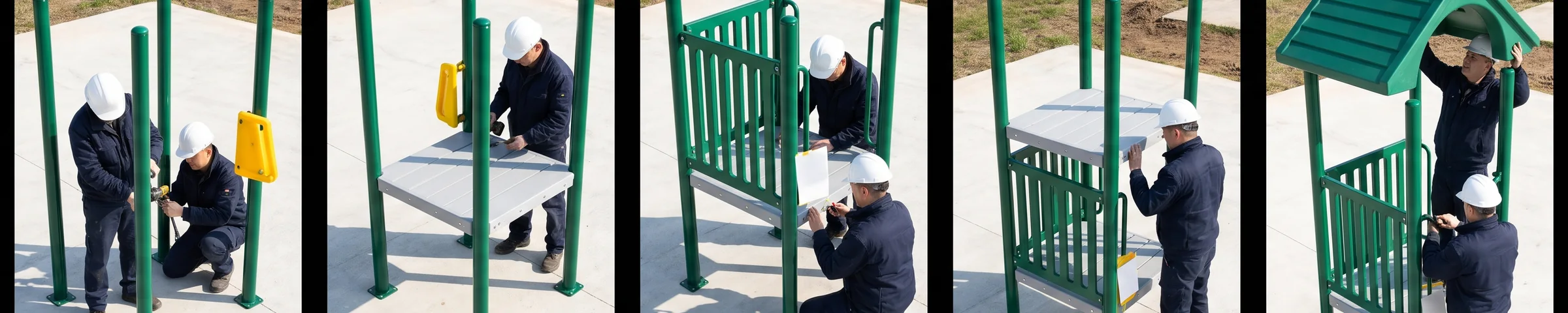
On the part
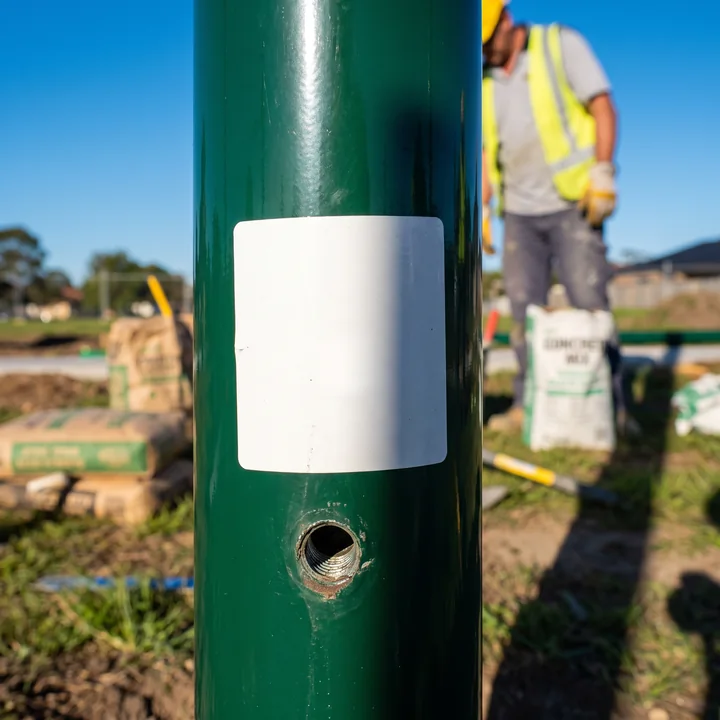 S1-014
Playground installation files and support for installers building commercial playgrounds, indoor soft play and trampoline courts from our equipment.
02/ 14Three rounds · 14 items · steps 01–10
Your installer receives the installation files in three rounds, so the job can be planned and excavated before the container arrives. The table shows every file, video and bag of hardware against the step of the on-site sequence it is used in.
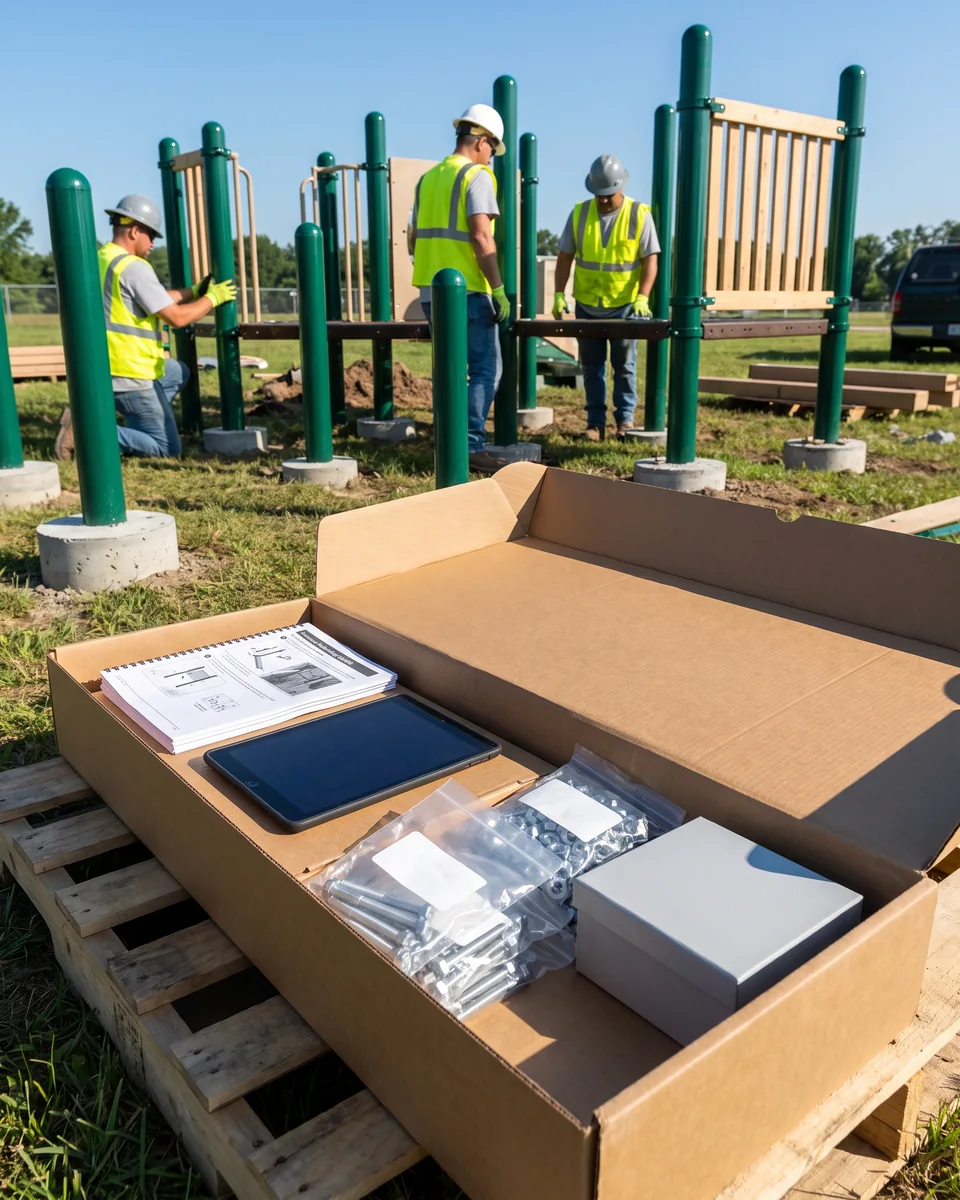 Installation package · S1
| Item | Round | 01 | 02 | 03 | 04 | 05 | 06 | 07 | 08 | 09 | 10 |
|---|---|---|---|---|---|---|---|---|---|---|---|
| Round 1 · Drawing approval day→ Excavation can start | |||||||||||
| Footing detail drawingsConcrete footing size for every post, shade posts and freestanding pieces | R1 | Step 01 | Step 05 | ||||||||
| Approved layout + footing points layerIn ft-in for US projects, mm for EN markets, or both | R1 | Step 01 | Step 03 | ||||||||
| Indoor frame anchor pointsMarked on the drawing for your structural engineer to confirm | R1 | Indoor projects · before the frame goes up | |||||||||
| Round 2 · During production | |||||||||||
| First cut of your installation videoReviewed with the pre-assembly photos and video | R2 | Your review point · before packing | |||||||||
| Tool listIssued with the drawings, so the crew arrives with the right tools | R2 | Step 01 | |||||||||
| Round 3 · With the shipping documents→ Before the container is opened | |||||||||||
| Assembly drawing set per structureExploded views, step numbers, part numbers, bolt sizes | R3 | Step 03 | Step 04 | Step 06 | Step 07 | Step 08 | Step 09 | ||||
| Final installation videoOne per structure, segmented by drawing step | R3 | Step 04 | Step 06 | Step 07 | Step 08 | ||||||
| General category guidesFootings, base plates, padding, beds, surfacing | R3 | Step 01 | Step 05 | Step 10 | |||||||
| Part list + packing listKeyed to part numbers | R3 | Step 02 | Step 03 | ||||||||
| Surfacing zone plan, area table, laying instructionsFor the surfacing materials in the shipment | R3 | Step 10 | |||||||||
| Inspection and maintenance guideIncludes the installer's completion checklist | R3 | Step 10 | |||||||||
| In the container | |||||||||||
| Equipment, numbered to the drawingPacked in installation sequence, by structure | Box | Step 02 | Step 03 | Step 07 | |||||||
| Anchoring hardware for every post | Box | Step 05 | |||||||||
| Spare kit with security bitsFasteners, caps, plugs, touch-up paint | Box | Step 09 | |||||||||
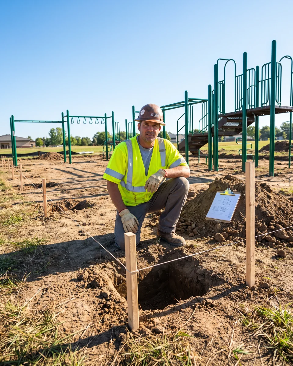 Footing detail drawing · on site
03/ 14Scope · six rows · one drawing
Both sides work from the same drawing. Each row below names the drawing that governs it, so the equipment in the container and the work on the ground meet in the same place.
| We supply | The same drawing | Your installer or contractor carries out |
|---|---|---|
| Layout and footing detail drawings | Footing detail | Site excavation and footing holes |
| Equipment, numbered to the installation drawing | Footing detail | Concrete footings, poured to the footing detail drawing |
| Anchoring hardware for every post | Layout | Local permits and inspections |
| Assembly drawing set and videos per structure | Assembly set | Installation labor |
| Surfacing materials with laying instructions | Zone plan | Laying the surfacing |
| Live video support and an optional supervisor | Checklist | Post-installation inspection with your playground inspector |
The full project timeline around this handover → How we build playgrounds
04/ 14Sheet · S1 · step 06
Each structure on your layout gets its own assembly drawing set: the playground assembly drawings your crew builds from. Structure S1 has one set, S2 has another, and a swing bay or fitness station has its own sheet.
The number in the exploded view is the number printed on the label of the part, on the packing list and on the box. A crew member reading step 6 finds S1-014 in the view, finds the same label on the post and fits it where the drawing shows.
S1-014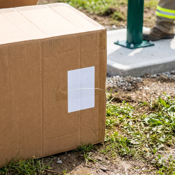 S1 · S1-014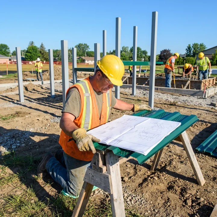
The finished structure and its footing positions.
Assembly steps in the order the structure goes up.
The parts that join at that step, pulled apart.
Every part in the view, in the {structure}-{part} format, for example S1-014.
Bolt sizes at each connection and the torque values, marked on the drawing.
Taken from the single-item plan and elevation.
The design office draws the set from the same model as your approved layout, so footing points, deck heights and use zones match it. A second designer checks the set against the standards checklist before it is sent, as described on playground layout design.
Trampoline beds carry cell numbers in the same way, for example T1-014, so the crew hangs each bed in the cell the drawing shows.
Send your site plan and ask for the installation package with your quotation. The layout and itemized quotation come back within 3 working days.
05/ 14Ten steps · outdoor structure
This is the order an outdoor play structure goes up in on your site, the playground installation sequence your crew follows from the first footing to the checklist.
Each step lists the drawing, the video segment and the numbers your crew works from, so commercial playground installation runs the same way on every structure.

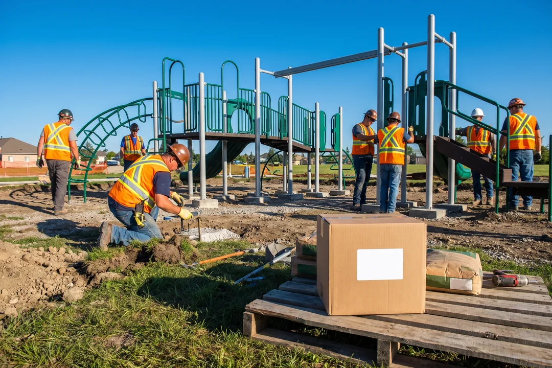
Your crew sets out the footing points from the layout and digs footing holes to the sizes on the footing detail drawing.
For anchor-bolt base plates, the footings and anchor bolts can be poured in advance to the same drawing. On a school site, removing old equipment and old footings is covered on school playground equipment.
Uses · footing detail drawing · footing points layer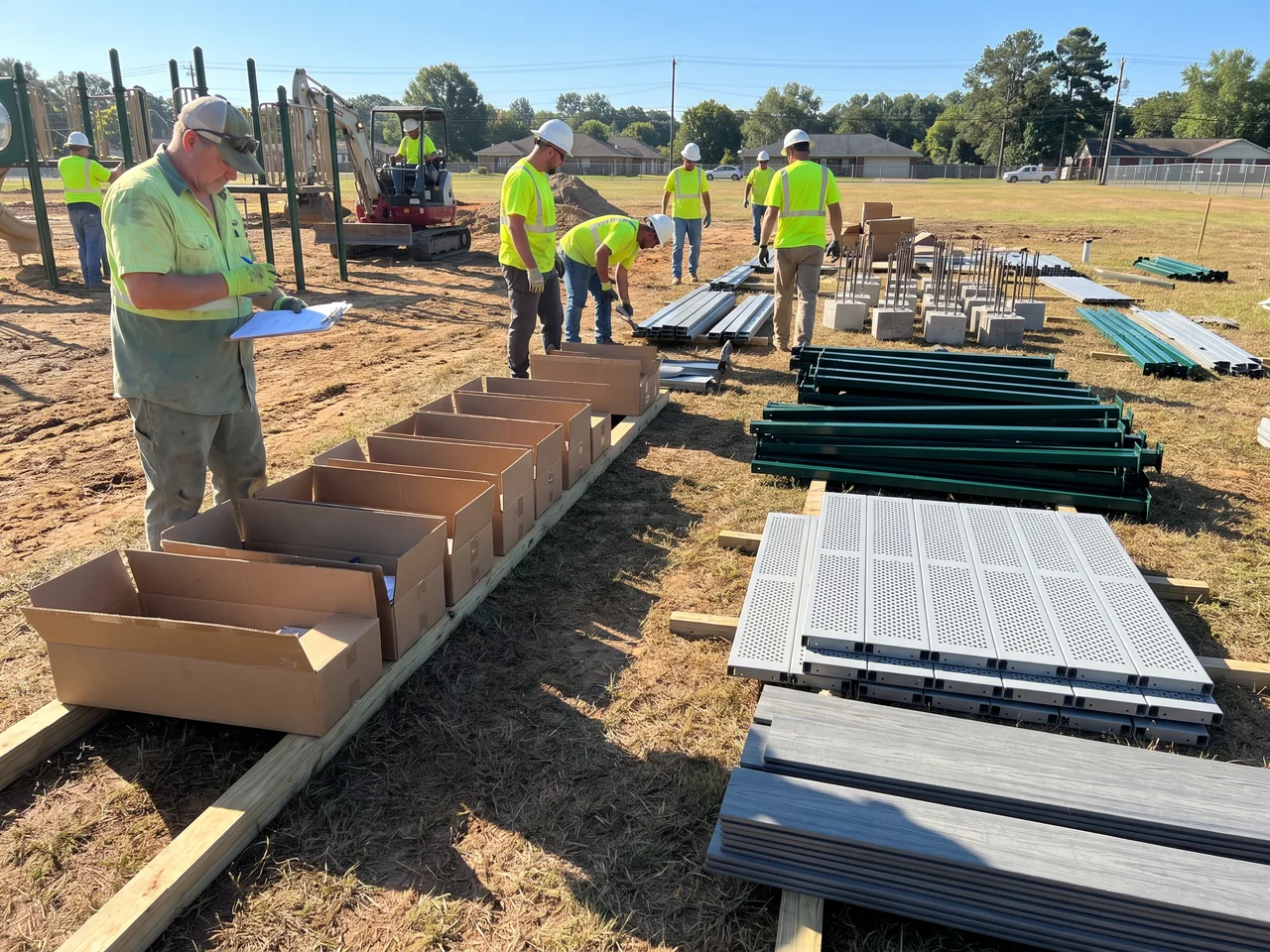
Parts are packed in installation sequence, so the boxes for S1 come out together, in the order S1 is built. Your crew checks each box against the packing list by part number. Anything missing or damaged is reported now, at unpacking, with photos and part numbers.
Uses · packing list · part labelsEach structure's parts are laid out next to its own footing points, grouped by the step they belong to on the assembly drawing.
Uses · assembly drawing steps · footing points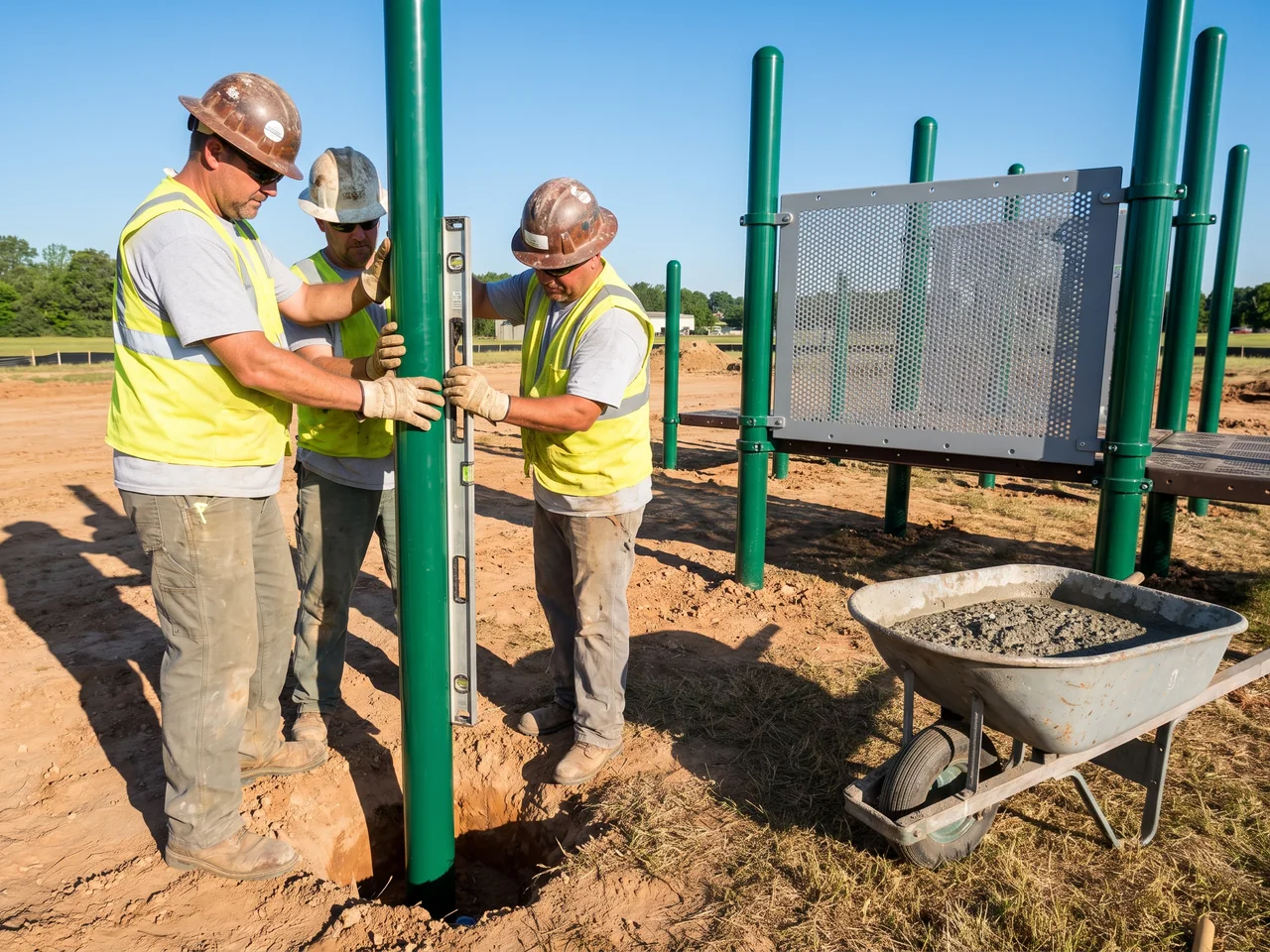
Posts go into the footing holes in the positions on the overview sheet, and the first deck connections are bolted in to hold them in position. The frame is set plumb and level to the deck heights on the drawing.
Uses · drawing steps for posts and decks · video segments with the same step numbersFor in-ground posts, the default, your crew pours concrete around the posts to the footing detail drawing once the frame stands plumb.
For anchor-bolt base plates, the base plates are bolted to the anchors. The concrete mix and curing follow your installer's concrete specification.
Uses · footing detail drawing · anchoring hardware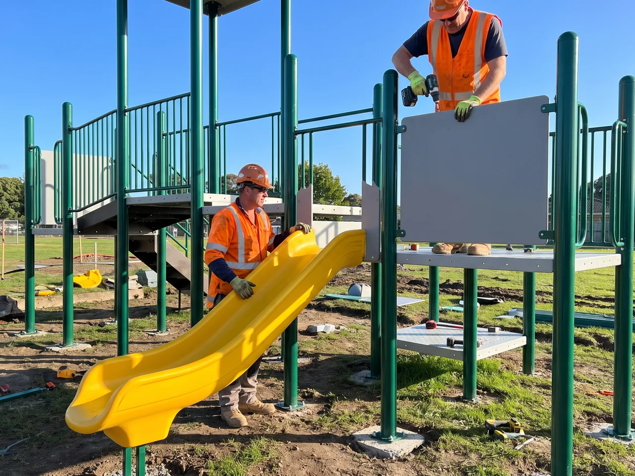
Punched steel decks with plastisol coating, steps, and the 19 mm HDPE barriers and play panels go on in the step order of the drawing. The holes in posts and decks were matched at pre-assembly in our yard, so parts go together as they did there.
Uses · assembly drawing steps · video segmentsRotomolded roofs, slides and tunnels are fitted to their deck and post connections by part number.
Uses · exploded view of each connection · video close views of the fixingsRope sections and climbing nets are fixed to their frames at the connectors shown on the drawing.
Uses · assembly drawing · video segment for the net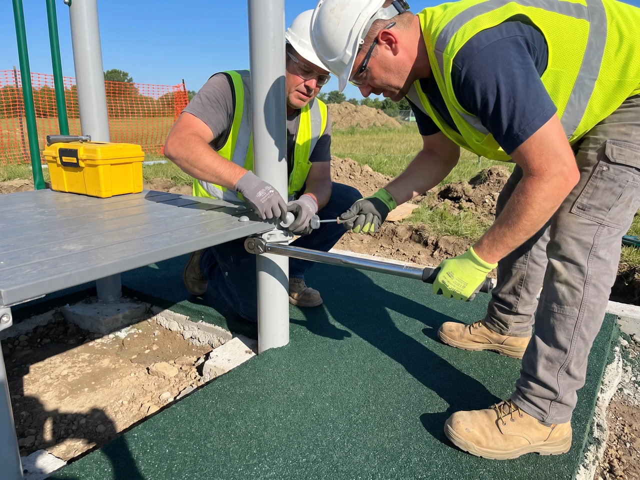
Every connection is tightened to the torque value on the drawing. The 304 stainless steel tamper-resistant fasteners are driven with the security bits from the spare kit, and every fastener head is capped.
Rotomolded post caps close every open post end, and plastic plugs close any exposed vent holes. Handling marks and any holes drilled on site are covered with touch-up paint in the structure's color.
Uses · torque values on the drawing · spare kitSurfacing is laid by your side to the thickness zone plan, then your installer works through the installer's completion checklist before your playground inspector visits.
Uses · surfacing zone plan and area table · inspection and maintenance guide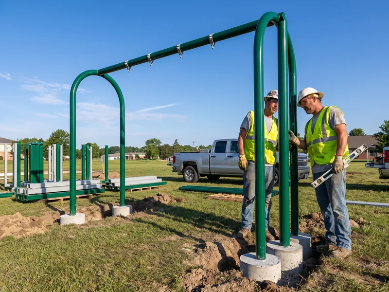
Swings, spinners, spring riders and fitness stations each have their own sheet and follow the same pattern: footing, frame or base plate, moving parts, tightening and caps. Their use zones on the layout show where each piece stands clear of the structures.
At every stage the drawing step, the video segment and the part numbers match each other.
06/ 14Video · cut from S1's pre-assembly
The installation video for each outdoor structure is cut from the pre-assembly and disassembly of that same structure in our pre-assembly yard.
When your structure stands in our yard, it is filmed going together in installation order, from posts to caps, so the video follows the order your crew builds in.
Close views show each connection, the bolt at each joint and the part number labels in frame, so your crew can read S1-014 on the screen and on the part in their hands.
The video is segmented by the step numbers of the assembly drawing. Step 6 on the drawing is segment 6 of the video. When your crew is on step 6, they open segment 6 and watch only the connections for that step.
Soft play, trampoline court and ninja course frames are trial-assembled in the same yard to check hole positions and connections, and that trial assembly is the footage for your frames. Padding follows the general guides.
Work that depends on your site, or that happens after the structure stands, is covered by general category guides that come with the project videos.
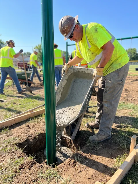 GuideFooting excavation and setting posts in concrete
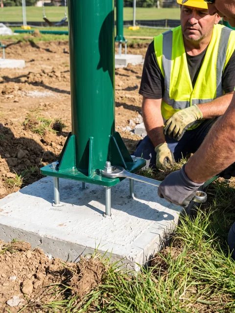 GuideAnchor-bolt base plates
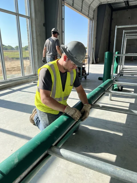 GuideSoft play padding fitted by part number
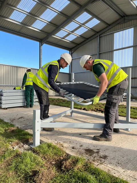 GuideHanging trampoline beds by cell number
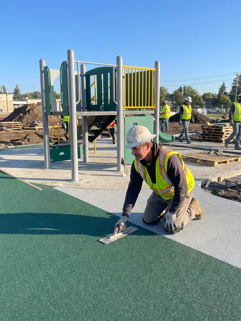 GuideSurfacing laid to the zone plan
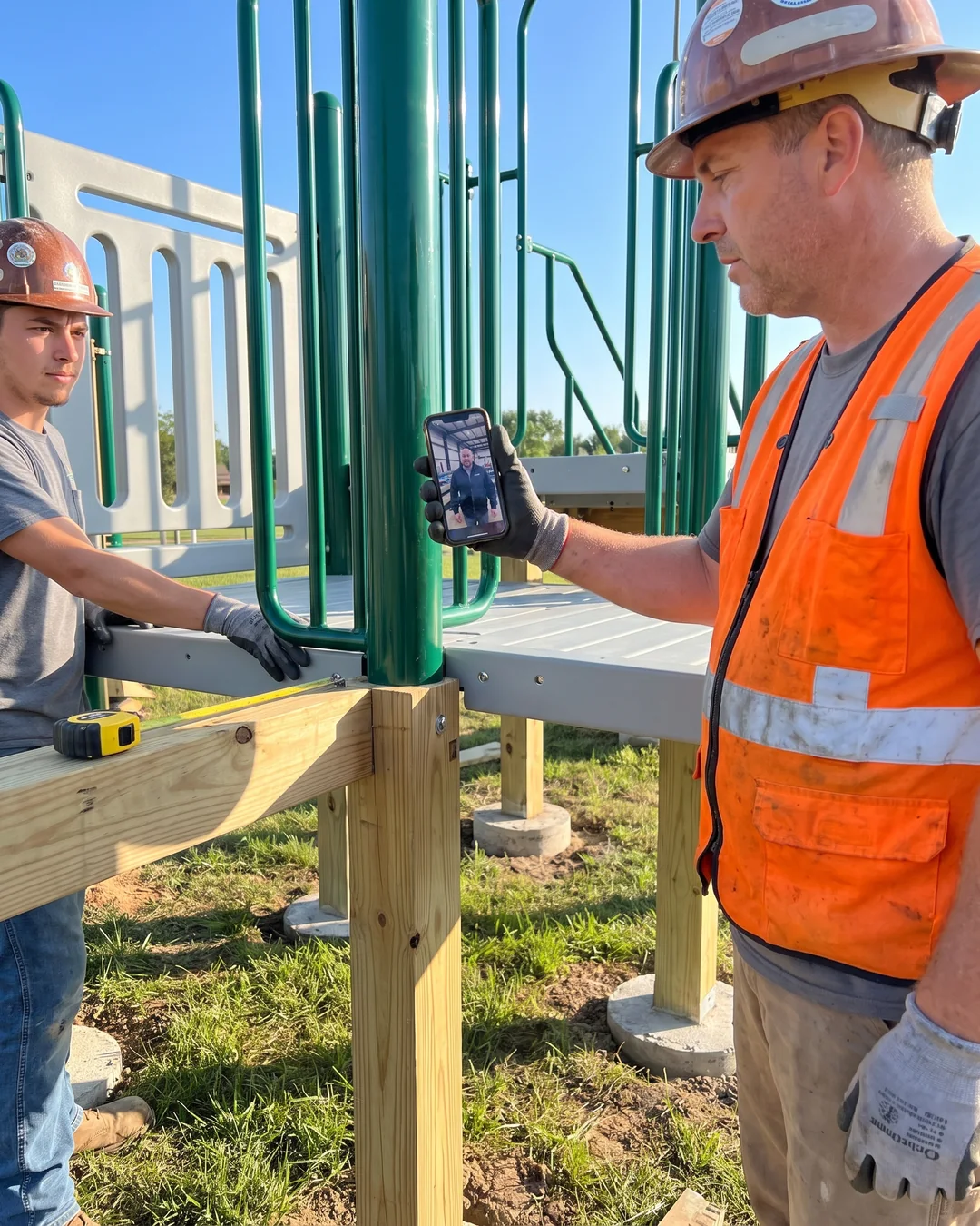 WhatsApp video · from the structure
07/ 14WhatsApp video · booked to your hours
When a step is unclear on site, your installer books a WhatsApp video call. Calls are booked to your installation hours, so your crew can call from the structure. This is playground installation support from the people who know that structure.

Takes the call and knows your order, drawings and packing list.
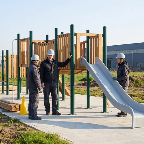
Joins for questions about the structure itself: the person who stood your posts and fitted your decks in our yard.
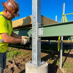
Step 06 · S1 · part S1-014 · photo attached
With the step number and part numbers, the yard lead can open the same step on your drawing and the same segment of your video before the call starts.
The yard lead talks your crew through the connection with your drawing and the part in view on the camera. If the question is a part that is missing, damaged or incorrect, the project manager takes the photo and part number and starts the replacement on the same call.
Your crew builds each structure from a video of that same structure going together.
08/ 14Supervisor · first structure
For a first project, a large site or a new crew, you can add an on-site supervisor. The supervisor comes from our pre-assembly yard team, the team that assembles every outdoor structure before it is packed.
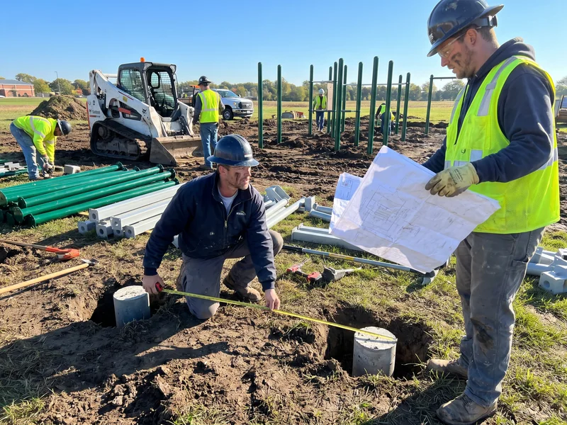
Before the posts go in, the supervisor checks the footing holes or anchor positions on site against the footing detail drawing and the layout.
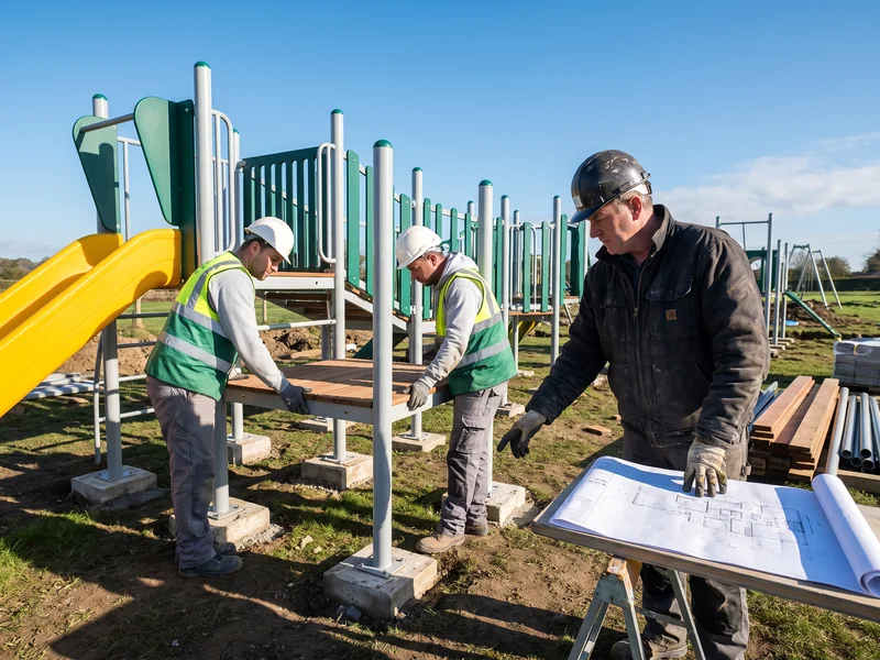
The supervisor builds the first structure together with your installers, step by step on the assembly drawing, with your crew doing the work.
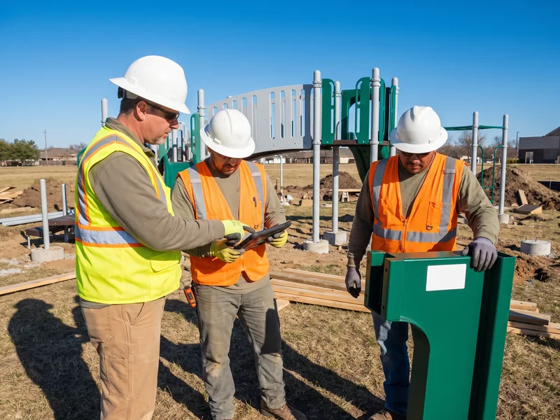
While building the first structure, the supervisor shows your crew how the drawings, part numbers and videos are used, so the following structures go up to the same method.
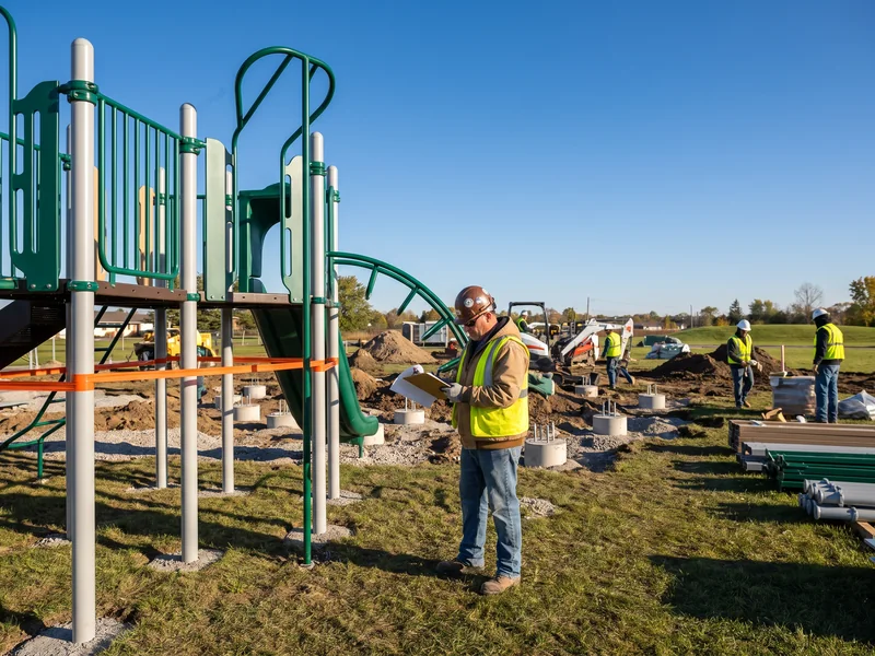
At the end, the supervisor signs off the installation checklist for the structures built.
The supervisor's on-site time is confirmed in the quotation for your project. Visa invitation, accommodation and local transport are arranged as listed in the same quotation.
The supervisor leads the first structure, and your crew finishes the rest with video support.
09/ 14Footing detail drawing · 3 methods
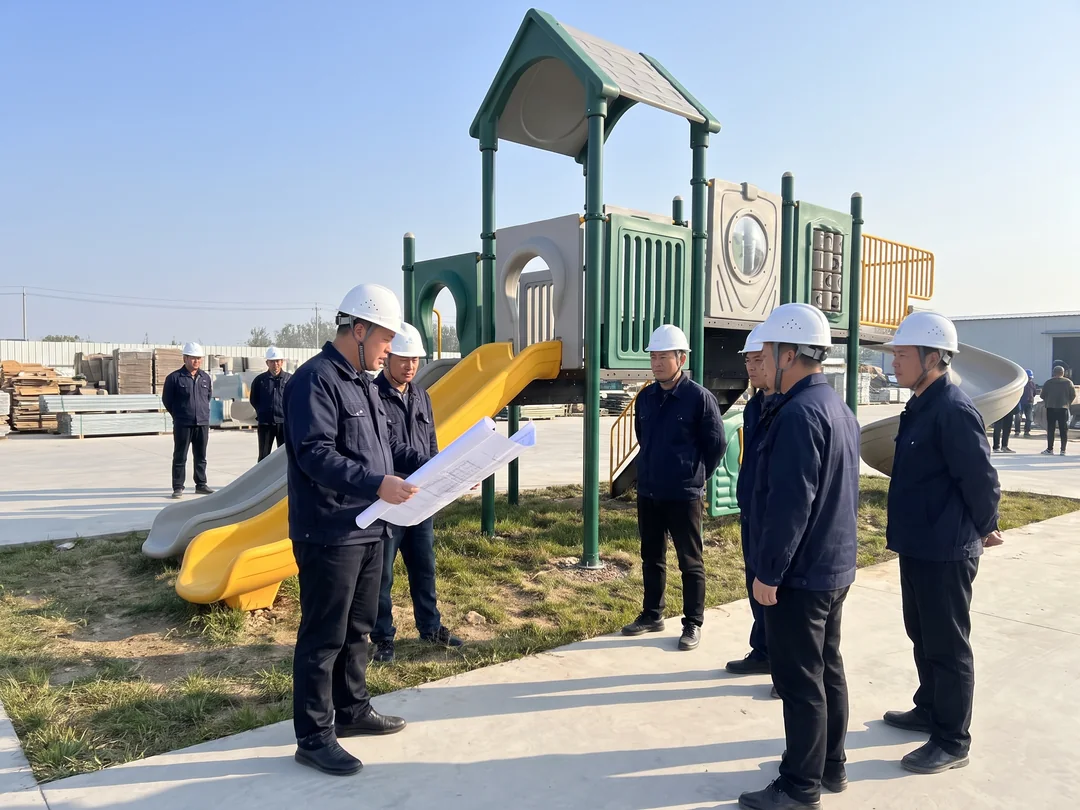
The footing detail drawing sets out how each post meets the ground, and your installer builds the footings to it. The method is chosen per project before production.
Ø114 mm galvanized and powder-coated steel posts are set into concrete footings. The footing detail drawing gives the size of each footing, and the footing points layer gives its position.
Posts can be ordered with base plates bolted to anchor bolts in the footing. The anchoring hardware ships with the equipment, and the drawing shows the footing and bolt positions. Base-plate footings can be poured and cured before the container arrives, and the structure bolts down on arrival.
Small freestanding pieces and low structures can take a surface-mount base plate, with the fixing confirmed by your structural engineer, as on preschool and daycare playground equipment.
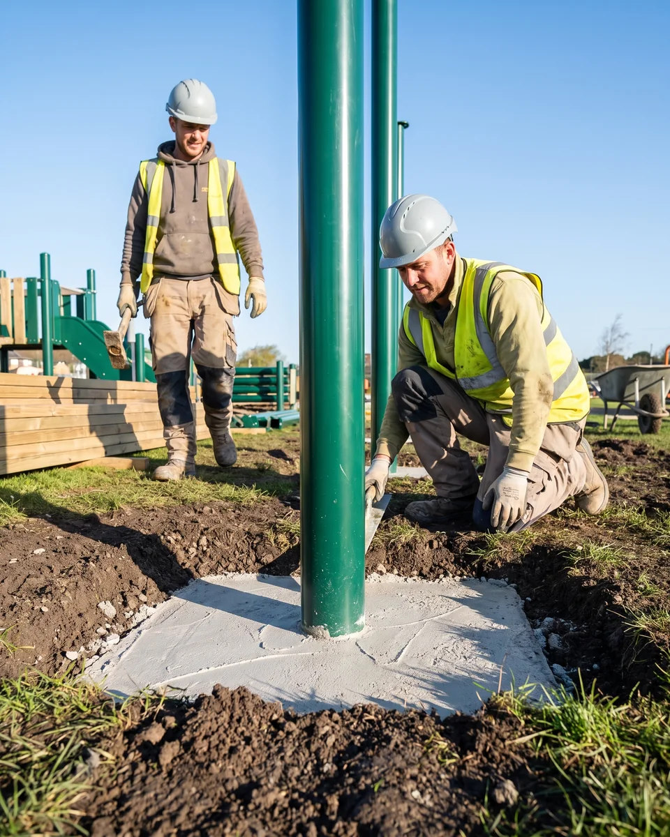
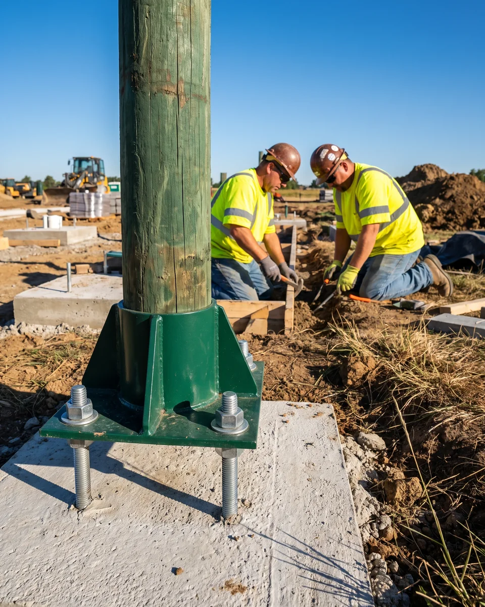
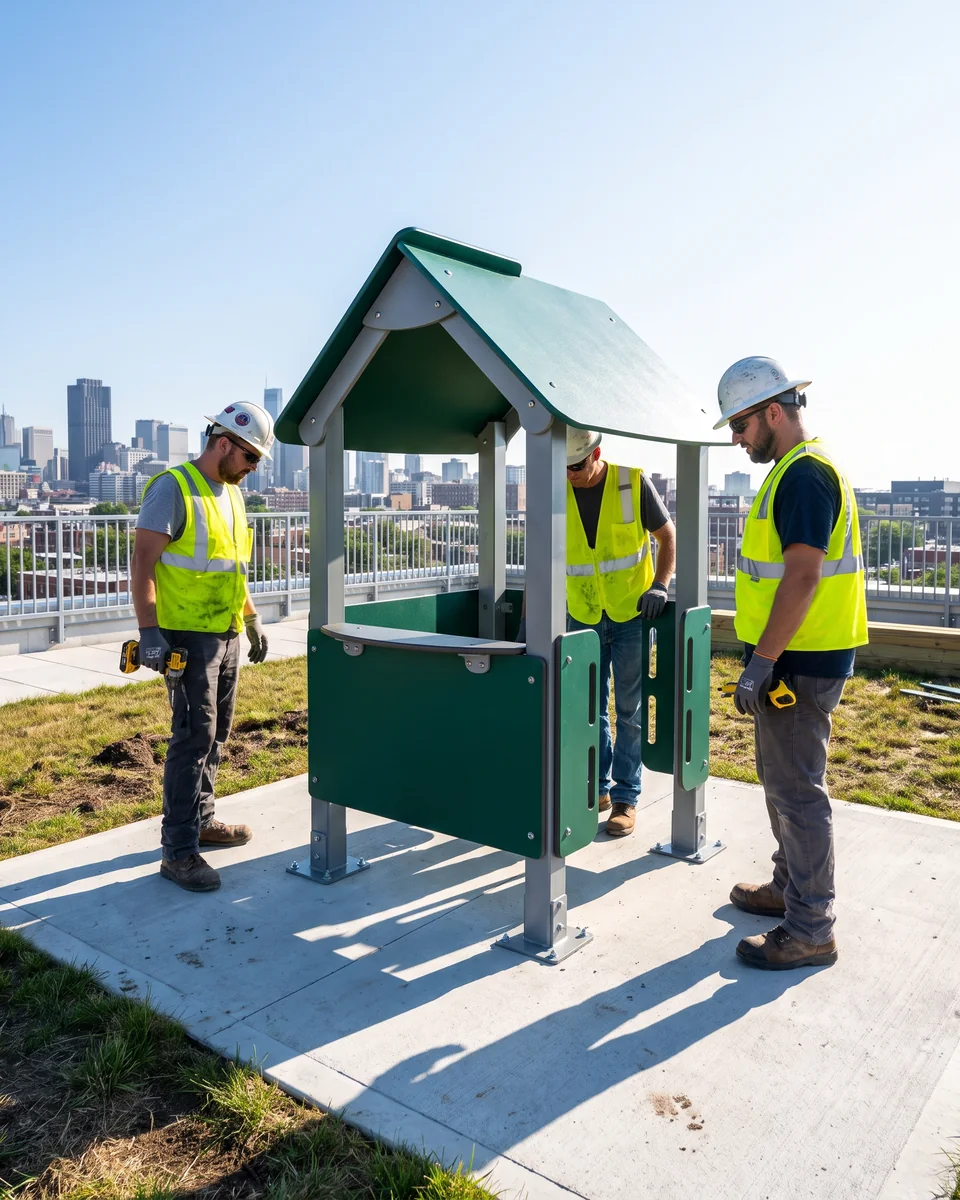 In-ground · concreteBase plate · anchor boltsSurface-mount
Shade posts, swings and fitness stations have their own footing sizes on the same drawing, so every hole on site is dug to a size your crew can read.
How footings are covered in the video guides → general category guides
10/ 14Spare kit · in every shipment
A tool list comes with the drawings, so your crew arrives with the right tools on the first day. Every shipment includes a spare kit, packed with the equipment.
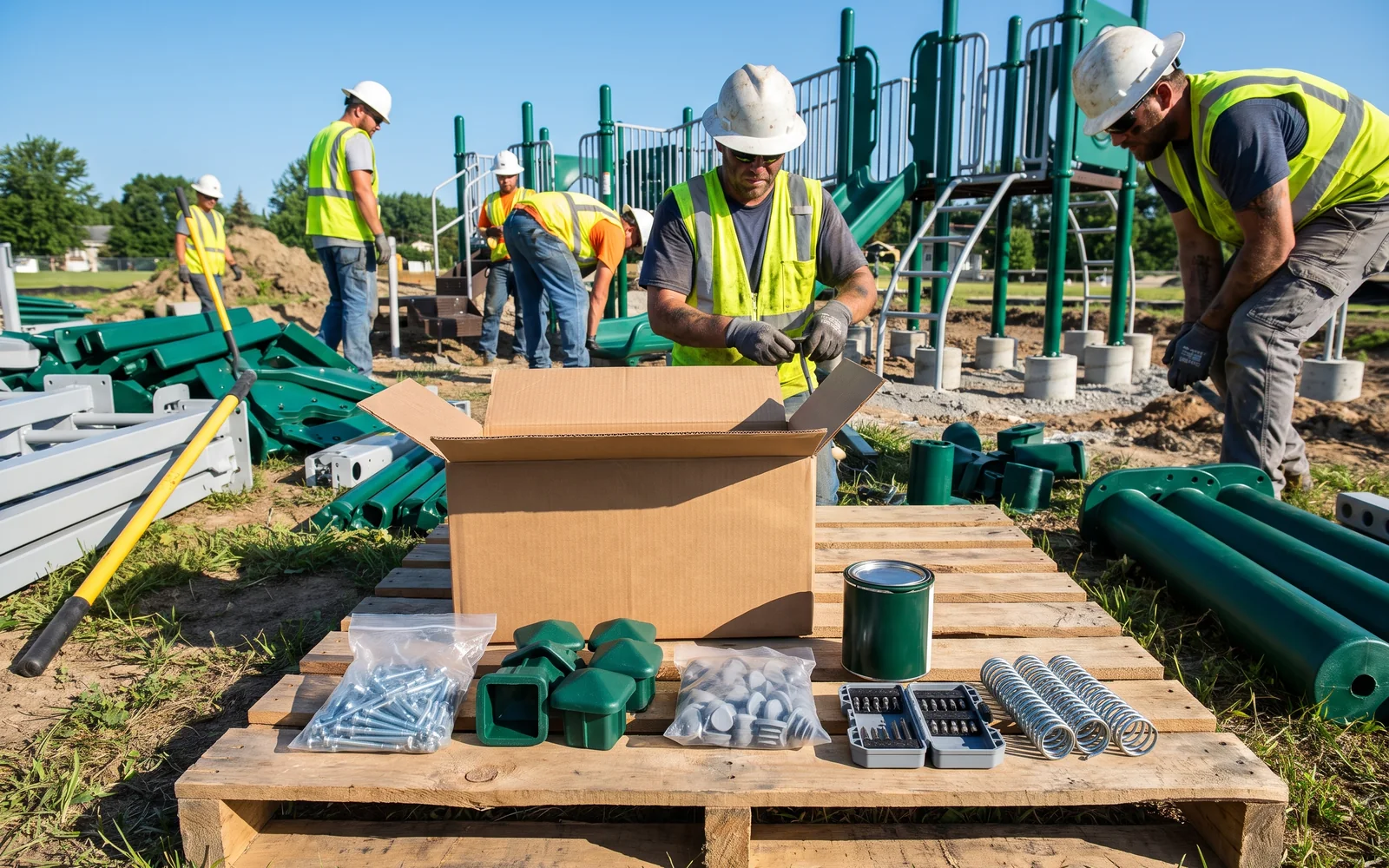
Issued with the drawings in production, before the container ships, so the right tools are on site the day the boxes open.
 S1-014
The part list is kept on file for your project, so a replacement for S1-014 is made to the same number at unpacking or years later.
11/ 14Indoor · frame first · padding by number
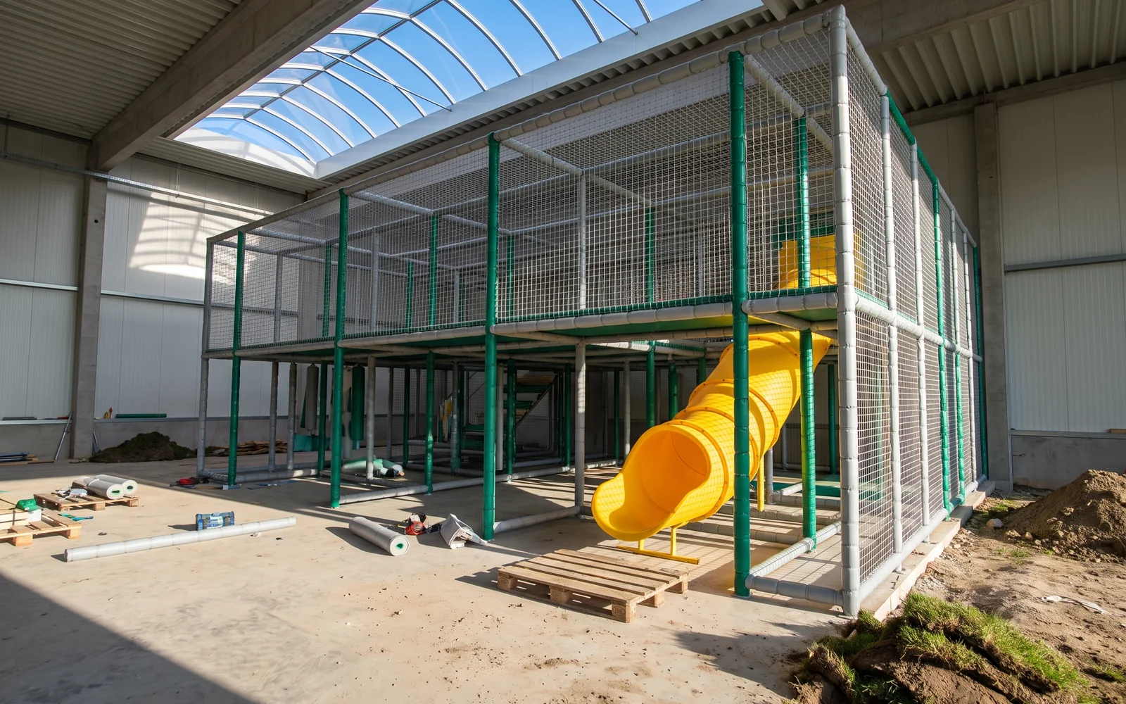
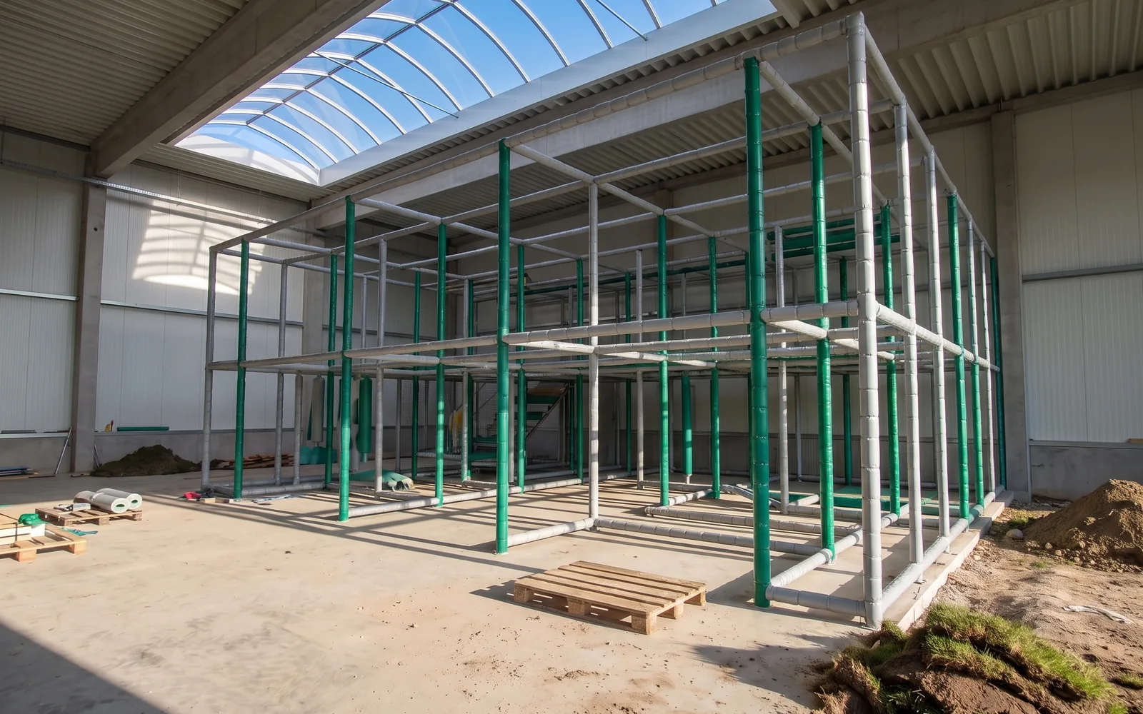
Soft play structures, trampoline courts and ninja courses go up in two stages: the steel frame, then the padding.
The Ø48 mm galvanized soft play frame, and the trampoline and ninja frames, are built from the assembly drawing set. Their hole positions and connections were checked at trial assembly in our yard, and the trial-assembly photos show part numbers.
Once the frame is complete, padding is fitted by part number. Every padding piece, net and mat is labeled with a number keyed to its structure, for example S2-021, and listed on the packing list, so the crew matches each pad to its position on the drawing.
The anchor points for each indoor frame are marked on the drawing, placed around your columns and entrances. Your structural engineer confirms the fixing to the floor or building structure before installation.
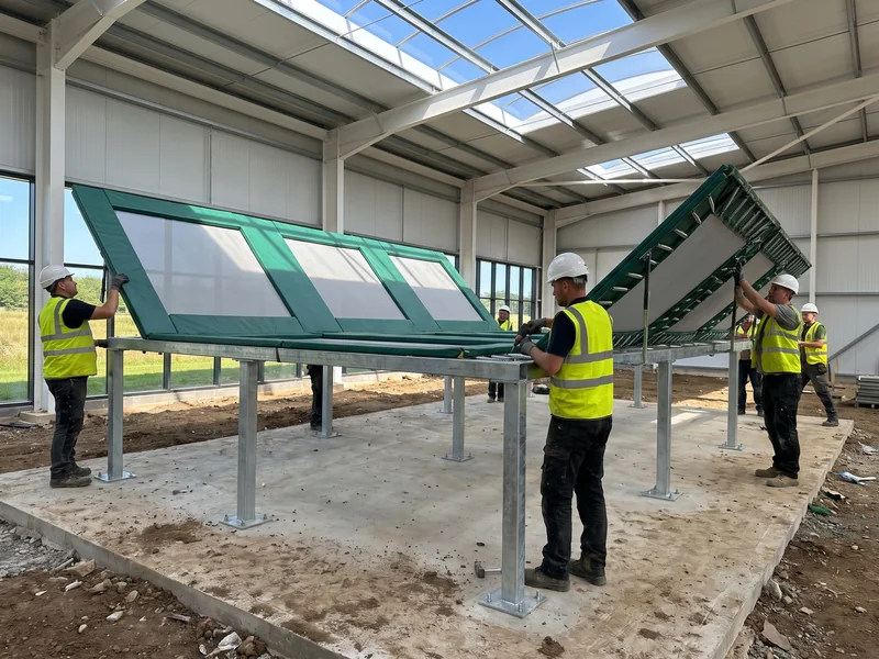
Raised courts are anchored to the floor slab, and in-ground courts are set into a pit built by your contractor to our drawing. Beds are hung by cell number, with spare springs in the kit, as covered on trampoline park equipment. Floor plans for whole venues are on indoor playground equipment.
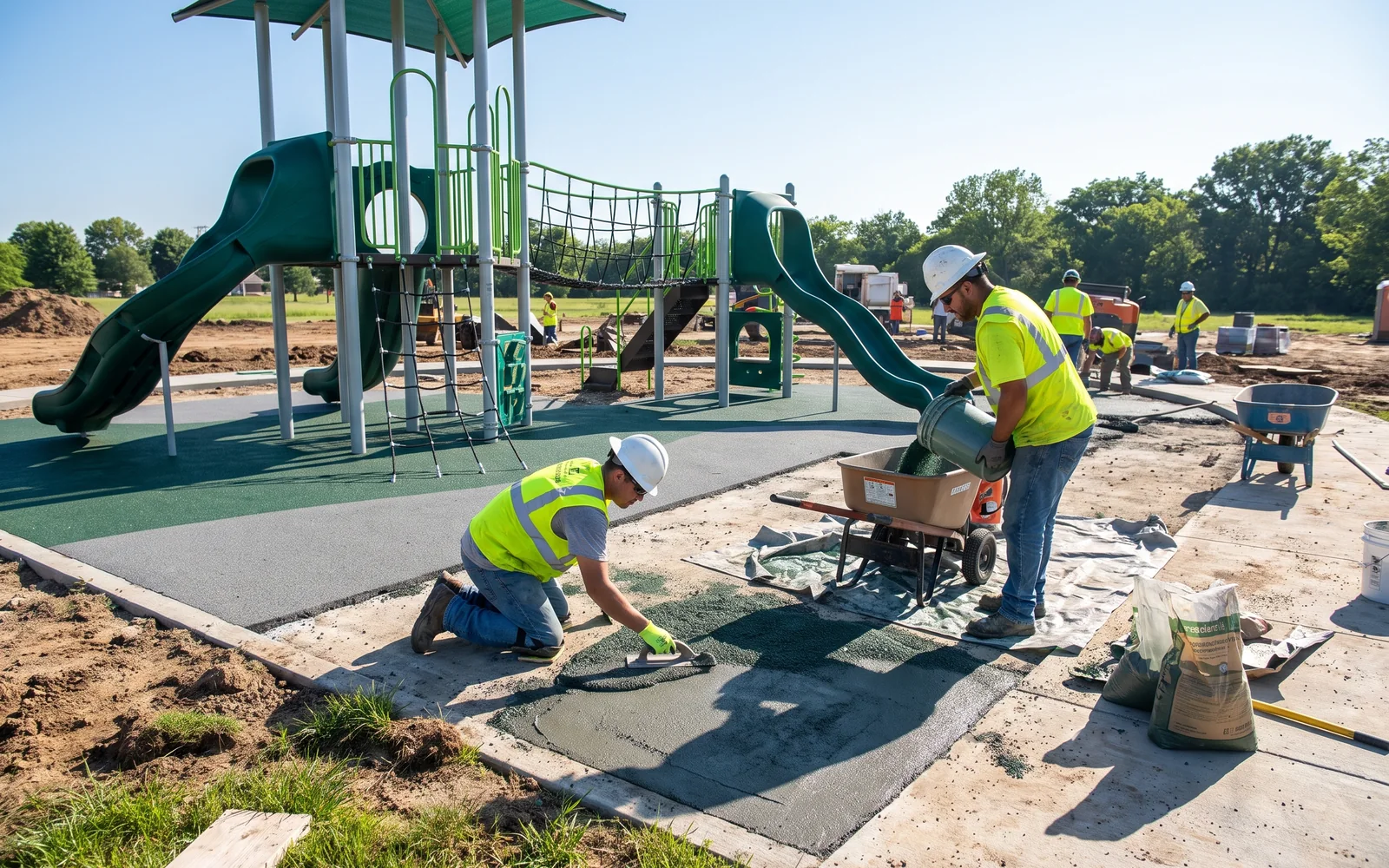
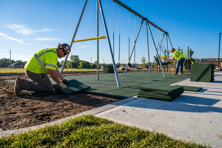
Poured-in-place EPDM or rubber tiles: the surfacing materials in your shipment are partner-supplied, with laying instructions for each.
Thickness is chosen by the critical fall height of the equipment it sits under. The zone plan is drawn from the use zones on your layout. Accessible surfacing on the accessible route is drawn to ASTM F1951.
The on-site surfacing thickness check is part of the post-installation inspection by your installer or playground inspector.
12/ 14Surfacing · laid by your side
Surfacing is laid by your side, from files and materials that come with the equipment.
Which thickness goes under and around each piece of equipment.
| Type | Zone | Area |
|---|---|---|
| Rubber tiles | Per plan | On your plan |
| Poured EPDM | Per plan | On your plan |
For ordering and laying.
For the partner-supplied rubber tiles or poured-in-place EPDM, with critical-fall-height data from the surfacing partner.
Surfacing products and standards → playground surfacing
13/ 14Installer's completion checklist · 6 checks
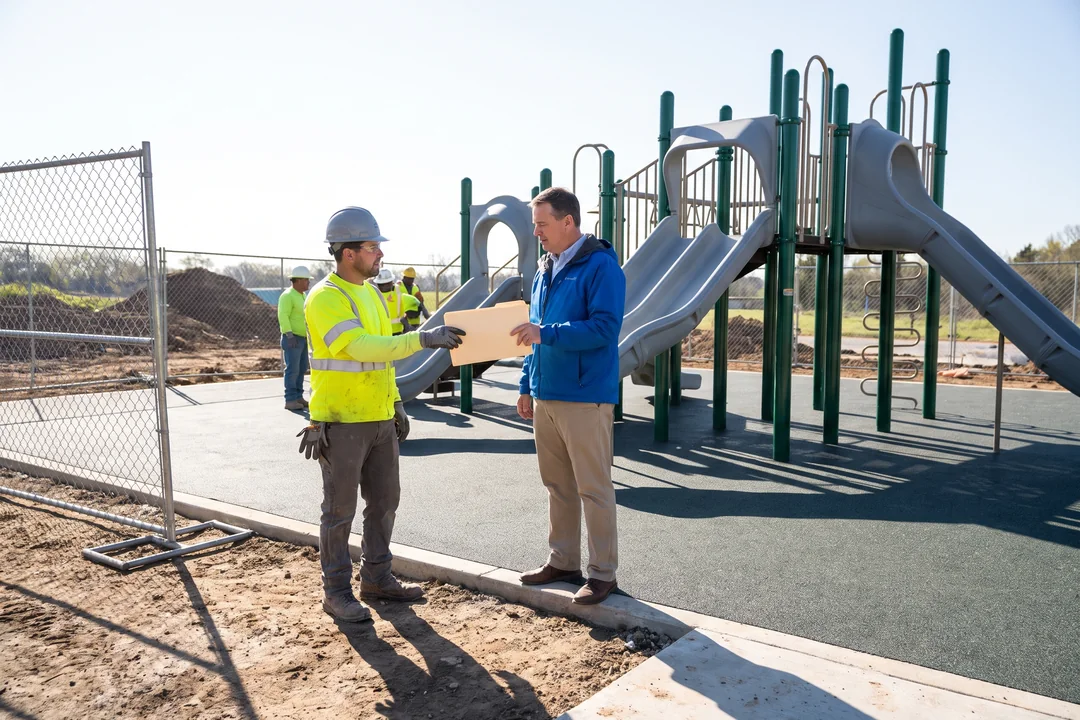
The inspection and maintenance guide in your project package includes an installer's completion checklist, for your installer to work through before your playground inspector visits.
What the installer checksTick as you go
/ 6
Checks doneReady for your playground inspector
The owner receives the inspection and maintenance guide for ongoing checks, and the installation drawing, part list and packing list for the site file. The post-installation inspection is done by the owner's installer or playground inspector against the use zones and deck heights on the drawing.
→ The site file
Standards and the compliance documents listed with each quotation → playground safety standards
14/ 14One file · two readers
Built for playground installers and contractors, dealers who install their own jobs, and the parks departments, schools, childcare centers and FEC owners who hire an installer for their site.
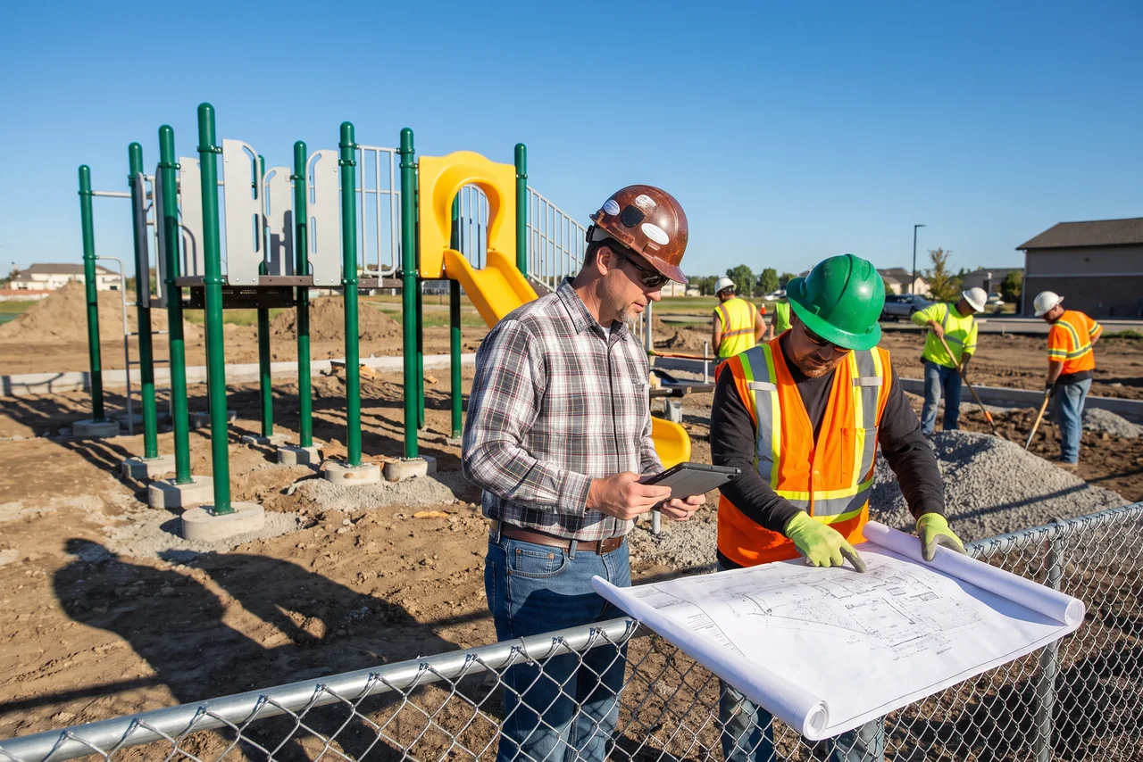
Parks departments, schools, childcare centers and FEC owners order directly and hand the installation package to their local installer.
The estimated installation labor hours per structure in the quotation, with the footing detail drawings, let installers quote the job and let you compare bids from playground installation companies against one figure.
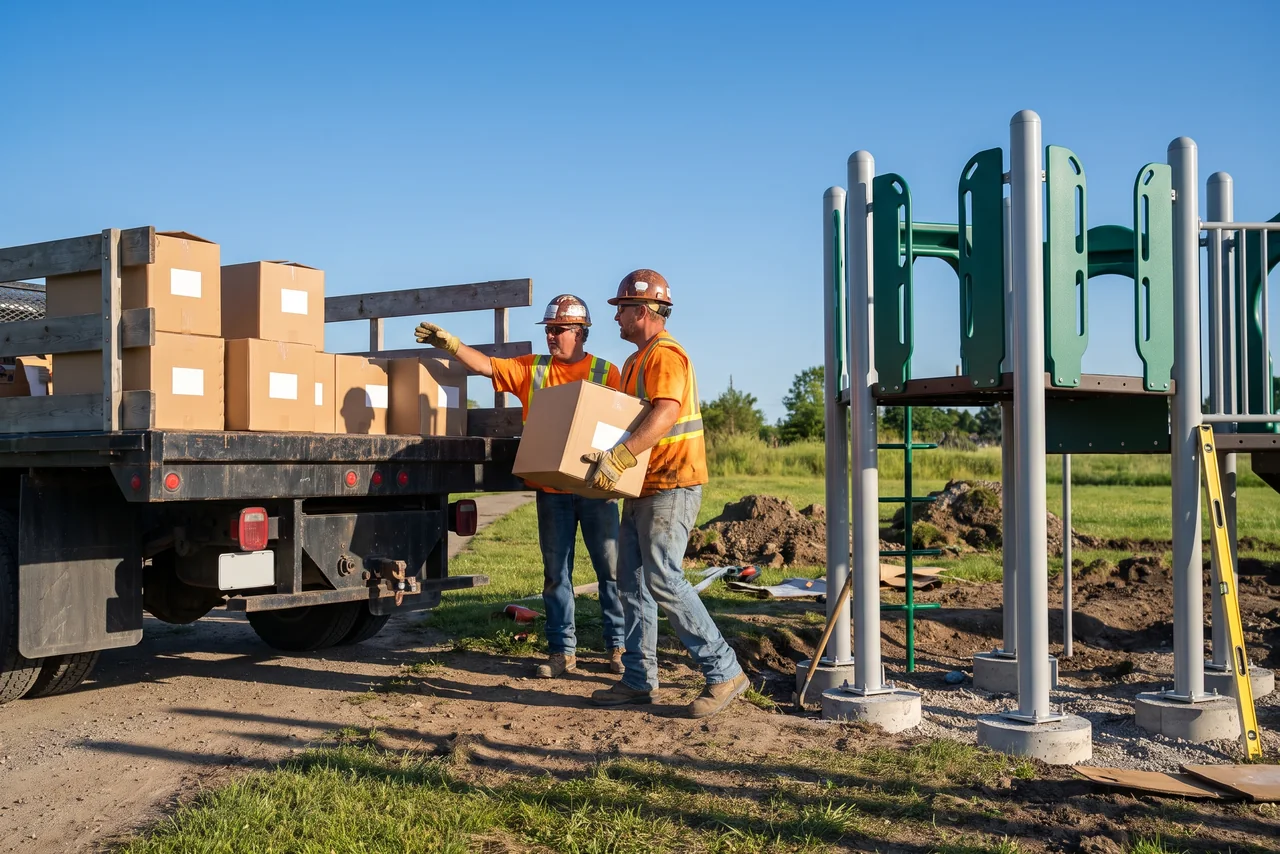
Installers send the site plan, receive the layout and quotation, and build from numbered parts with video support. Dealer and installer terms are on wholesale playground equipment; outdoor ranges are on commercial playground equipment.
Phase 2 jobs are ordered to the same project file, so drawings and part numbers continue from phase 1.